Properties of BGO
Density 7.3 gm/cc.......... Effective Z 83
Decay time 300 nsec...... Refractive index 2.13
Hardness 5 Mho............. No cleavage planes
15% light output of NaI. Atten. len. 1.1 cm @511 keV
First use of BGO detectors in PET scanners
1. Thompson C J, Yamamoto Y L and Meyer E: "Positome II: A high efficiency positron imaging device for dynamic brain studies." IEEE Trans Nucl Sci NS-26:1: 583-589 (1979)
2. Roney J M Thompson C J: "Detector identification with four BGO crystals on a dual PMT" IEEE Trans. Nucl. Sci. 31: 1022-1027 (1984)
3. Lupton L R, Keller N A, Thompson C J, Anderson L L: "On the use of tapered BGO crystals in PET" Nucl. Inst. and Meth. in Phys. Res. 227 361-368 (1984)
4. Thompson C J, Roney J M, Lecomte R, Schmitt D, Lupton L R: "Dependence of the coincidence aperture function of narrow BGO crystals on crystal shape and light encoding scheme" Phys. Med. Biol. 31 491-506 (1986)
Properties of BGO Density 7.3 gm/cc.......... Effective Z 83 Decay time 300 nsec...... Refractive index 2.13 Hardness 5 Mho............. No cleavage planes 15% light output of NaI. Atten. len. 1.1 cm @511 keV |
|
|
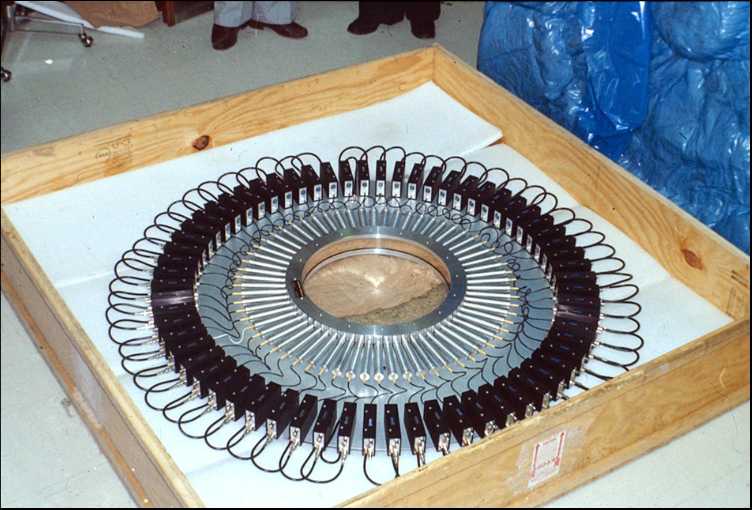
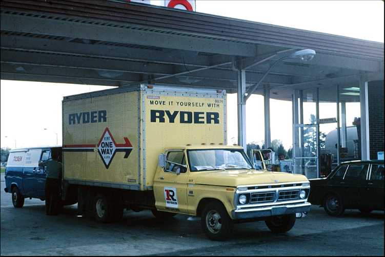
| Bismuth germanate (BGO) was first proposed as a useful scintillator for PET by Cho and Farukhi in 1977. Its excellent stopping power, transparency, and ease of handling all suggested that it would be superior to NaI which had been used in previous PET scanners. This paper appeared at a time when the first PET scanner was being used for blood flow studies with 77-Kr, and since this was hard to get in high quantities, a much more efficient scintillator seemed like a good thing. | This is a picture of the first detector ring of Positome-II as it was being packed to bring to Montreal from the Harshaw factory in Solon, Ohio in May 1978. The 64 BGO crystals had been ordered in November 1977, and the amplifiers (black boxes and wires), and other components ordered in February 1978. Drs M Farukhi, and Frank Wilkinson and their team had managed to build and test the whole assembly in a very short time, especially considering that this was the first time so many BGO crystals had been grown, cut into a trapeziodal shape and polished | This project was carried out in a great rush so that we would have the first BGO PET scanner ready to show at one of the first ever PET symposia being held at the Montreal Neuro in June 1978. In order to save time, Ernst Meyer and I flew to Cleveland, and rented this truck in which we drove the detector array back to Canada. Since my then six year old son Philippe had the initials P E T, he came along for the ride as a "good luck" charm!. |
|
|
|
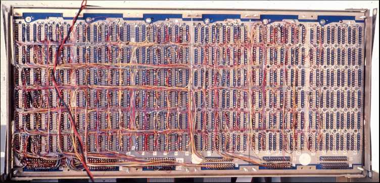
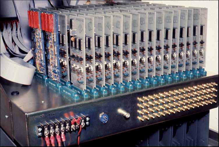
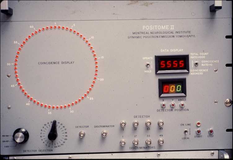
| This picture shows the wire-wraped coincidence circuit underside which was designed and wired at the Montreal Neuro. while the detectors were being made. Although the basic flow of this circuit was quite similar to the one we acquired from Brookhaven, it had to handle twice the number of detectors and had to be very much faster. I designed it, using mostly high speed Schottky TTL ICs which were just becoming common then. The wire wrapping was done by Janet Arts and Pat O'Reilly, two lab. technicians who worked for Dr Yamamoto. They had no previous electronics experience, but became pretty good at trimming the wire to the right length and making the right connections. To help debugging, and to make life more interesting for them I chose different colours of wire, and the colour corresponded to the resistor-value numerical colour code of the last digit of the signal name. Since the signals were more or less in order from each detector, this minimized the number of wires with the same colour which followed similar paths, making the wires much easier to follow. | Discriminator rack. The actual discriminator circuit boards were built and tested be Harshaw, but the mounting rack and wiring were made by George Lootus at the Montreal Neuro. The gold connectors to the right connected the preamplifiers on the detector ring to the corresponding discriminator. The grey ribbon cables at the left went to the front panel LEDs, the coincidence circuit and the numeric display. | George Lootus also wired up this front panel and had all the holes drilled. The red ring has 64 LEDs and the one corresponding to the crystal was lit each time a gamma ray was detected. The display showed the count-rate in kcps (or it could also show the address of the last two coincident crystals to help troubleshooting). When the count-rate was very low, (at background levels) one could see the individual LEDs wink on and off, but during a normal study, they all glowed fairly uniformly. If something went wrong, like a leak of the Kr-77 gas which the patients inhaled for blood flow studies, the upper LEDs glowed much more brightly than the rest. |