|
| Image-guided Neurosurgery is a surgical planning technique whereby a volume model of a patient's head is constructed from a set of segmented MRI or CT images and is then registered with the patient's head in the OR using a locating device. Successful guidance depends on the accuracy of the transformation between the graphical and patient spaces, which unfortunately degrades under brain tissue shift and extrusion. |
 |
 |
 |
| Semi-automatic anatomical surface identification. | Range-sensing of skin and cortex in the OR. | Rigid registration of the skin range image with its MRI/CT homologue, which will serve as a baseline for the next stage. |
 |
 |
| Non-rigid motion tracking, over time, of the cortical range image. | Interpolation of the resulting surface displacement over the whole brain volume, assuming null displacement at the base of the skull, via a realistic finite element model (FEM). |
 |
 |
 |
| Illustration of an embedding of 2D contour identification into 3D, a notion which extends to imbedding 3D surfaces into 4D. | Skin surface identified from an inward moving front originally initialized as a cube coinciding with the scan perimeter. | Cerebral surface identified from an outward moving front originally initialized as a series of small spheres in the white matter. |
In general, a surface evolution model is initialized by a user-defined surface completely inside (or outside) the desired anatomical boundary. The front then moves in a strictly outward (inward) manner and features a diffusive term which tends to smooth out the front, a hyperbolic term which pushes the front forward, and two image terms which halt the front at strong gradients. The user-defined surface is processed in the initialization by computing from it a signed distance function, with interior points typically labelled negative, and exterior points positive. Typical results for skin and brain surfaces are shown here. For further information, consult the webpages of either Kaleem Siddiqi, Ron Kimmel, or James Sethian.
Using Fast Marching Level Sets to Compute Distances and Closest Points
The distance function computed from the initial user surface is implemented by a fast marching level-set
method which estimates the arrival time of a monotically advancing front. By using a constant unit speed,
this arrival time function corresponds to a sub-pixel Euclidean distance map. Next, to reduce the
complexity of computing a 4D, rather than 3D, function, we adopt the narrow band approach proposed by
David Adalsteinsson. This technique restricts the computation of the
evolution equation to the part of the domain near the zero level-set, or near the evolving 3D surface.
This band is also determined by fast marching methods, which amounts to computing a distance function from
the evolving 3D surface.
Moreover, the propagative nature of the fast marching algorithm can be exploited to reveal which surface point is closest to a given voxel (i.e.: which surface point possesses the shortest arrival time). This characteristic is useful for the registration later on, as it results in a set of explicit point pairs which lead to a closed-form transformation computation, rather than a lengthy search for optimal transformation parameters which best account for a set of shortest distances. A closest-point map is therefore also computed for each final anatomical surface which we intend to register.
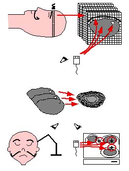
The three-dimensional coordinates of the visible surfaces of the skin and evolving cortex are computed by a commercial range-sensor made by Vitana Corp. (Ottawa, Canada), which uses both laser-based triangulation and defocusing techniques to estimate range. Laser-based range-sensing is the industrial standard for quickly and accurately acquiring dense, quantitative information on 3D shape. The sensor is mounted on a commercial linear positioner, made by Intelligent Actuator. A range image of a human left hemisphere, acquired with this sensor, is featured below.
Laser-based triangulation involves projecting a thin ray of laser light onto an object, capturing the reflected light by a charge-coupled device (CCD), and inferring depth from the pixel position of the reflected point and from the geometric relationship between the position of the laser source and the CCD (as shown in the left image below). Ordinarily, this ray would have to be swept along two axes normal to each other and spanning the anatomical surface of interest. However, our sensor dispenses with one sweep axis by optically spreading the ray into a laser plane. The intersection of this plane with the imaged object instantaneously produces a 2D range-map of a slice of the surface, which appears as a curve of 256 points, or laser profile, on the CCD. A 3D surface is then obtained by linearly sweeping the sensor, ideally in a direction normal to the laser plane, across the surface of interest.
 |
 |
| Triangulation geometry. | Defocusing geometry. |
 |
| Range-sensing setup. |
In our sensor, defocusing is implemented by allowing the laser light to pass through two holes, at a predetermined distance apart, rather than one. The CCD sees two laser profiles instead of one, and range is determined by measuring the space b (in each pixel column) between the two images of a laser point, as illustrated below, from an inverse relationship between range z and b. The range measurements obtained by triangulation and by defocusing are combined by assigning weights to the two expressions for range. For further detail, consult our SPIE Medical Imaging 1999 paper.
The goal of this procedure is to exploit temporal curvature consistency to produce a displacement map of the cortical surface, as well as the likely area of extrusion (whose curvature is inconsistent), which can then be used to update the equivalent surface on the original graphical model. Furthermore, this surface displacement will be used as a boundary condition for the FEM in order to estimate the volumetric displacement.
Subsequently, a rigid-body refinement, at t0, computed by an {\it iterative closest point} (ICP) technique (for further detail, consult our forthcoming Medical Image Analysis paper), can bring into precise alignment the range image of the skin and its homolog identified semi-automatically in the MRI scan. Our iterative registration technique is characterized by a distance map being precomputed for the MRI volume from the identified cortical surface, thereby accelerating the computation of distances between closest-point pairs, rather than imposing an expensive search for them. In contrast, closed-form methods for computing transformation parameters all require explicit point-pairs, not distances between them. We make use of the fast marching level-set method to produce a dense map of both closest point labels and the distances to them, allowing us to do away with a search for closest points as well as producing explicit point pairs which can take advantage of closed-form transformation algorithms, thereby making each iteration of our ICP technique essentially instantaneous.
The justification for emphasizing computational efficiency here is two-pronged: clinical acceptability and the inherent temporal underdetermination in estimating non-rigid motion. In order to make the non-rigid motion estimation well-behaved, the smoothing parameter is initially set very high, and is gradually lowered as the process iterates, progressively resolving finer-level motion detail. Just as for the rigid ICP stage, each iteration of the non-rigid surface motion estimation is essentially instantaneous.
For the purpose of reproducing non-rigid cortical movement, we have implemented a brain-shaped phantom with elastic material properties. We use a brain-shaped jello mold , into which we pour PolyVinyl Alcohol Cryogel (PVA-C) , as illustrated below. This is a relatively viscous liquid, which upon freezing and thawing, becomes an elastic solid. This phantom rests on a support plate of plexiglass (usable within an MR scanner), and features a moving assembly consisting of a small disk and rod, also of plexiglass, imbedded within the elastic material, as well as some glass beads used to validate the surface displacement/FEM approach to volumetric motion estimation.
 |
 |
| PVA-C in liquid state being poured into brain mold. | Resulting brain-shaped elastic phantom, after freeze-thaw cycle. |
In order to assess non-rigid surface tracking, we turn the set screws under the support plate of our elastic phantom, triggering a deformation of up to 15mm at the top, and image the cortical surface with our range-sensor, while maintaining the support plate fixed with respect to the range-sensor/positioner reference. We then compare the results of a strictly rigid transformation computation with a sequence of rigid and non-rigid ICP registrations, using a rough initial alignment based on the corners of the range domain.
 |
 |
| Typical registration results with deformed phantom: MRI level-set surface rigidly registered to the range image of the deformed phantom. | MRI level-set surface non-rigidly registered to the range image of the deformed phantom. |
 |
 |
 |
| Slice through top left image, at y=79.592. | Slice through top right image, at y=79.592. | Evolution of RMS point-pair distance with ICP iteration. |
 |
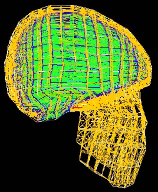 |
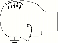
| The finite element modelling we will adopt for estimating volumetric intrasurgical motion is a static analysis with known boundary displacement on a surface patch of the cortex, and assumed null displacement at the base of the skull. | In order to propagate the surface displacement information to the rest of the volume, we will use a FEM whose elements reflect realistic properties of brain tissue (grey and white matter), dura mater, cortico-spinal fluid and bone. Several such models have been published, including those of Albert King et al. of Wayne State University (his student Jesse Ruan's model is shown here) and Mike Miga of Dartmouth College. |
| Now in order to make the model adapted to the patient's anatomy, we must construct the elements based on which anatomical surfaces, such as appear on the right, their constituent nodes fall in. This is an instance of the meshing problem. Clearly, we are only interested in tissue types which are identifiable and therefore segmentable in the MRI/CT scan, and especially those which are materially relevant to the simulation. | 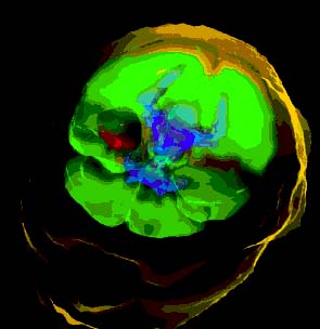 |
This approach to compensating a graphical model for deformations has another extremely attractive side-benefit: the realistic FEM used to propagate surface information to the rest of the volume can also be adapted to implement a virtual suction aspirator (or a scalpel) as used in the operating room, in the context of surgical simulation. There is research currently being conducted at McGill on haptic feedback and surgical simulation , and a collaboration on patient-specific surgical simulation is foreseen.
Clinical validation of the cortical surface tracking-FEM approach is planned in the near future, after skin registration and meshing issues are resolved.