MNI Display - Software for Visualization and Segmentation of Surfaces and
Volumes
Robert D. Vincent, Athena Buckthought, and David MacDonald
June 29, 2016
Contents
1 Introduction
MNI Display is a program originally written by David MacDonald as part of this thesis research while a student at
the McConnell Brain Imaging Centre. The program was designed to display and manipulate three dimensional
objects, mainly human cortical surfaces and sulcal curves. It has evolved to include visualization and segmentation
of 3D and 4D medical images. The user interface is a non-standard menu oriented system based on keystrokes and
mouse (or touchpad) operations.
1.1 Visualization features
MNI Display supports a large number of visualization features.
- Overlaying multiple volumetric images irrespective of differences in their sample grid sizes. For
example, you can display a 4D functional PET or fMRI image overlaid on a high-resolution 3D
structural image.
- Visualization of 3D surfaces, such as cortical surfaces produced by CIVET, and the intersection of the
3D surfaces with the volumetric data.
- Displaying an arbitrary, oblique plane through the volumetric data.
- Flexible choices for mapping from voxel data to colours.
- Associating arbitrary per-vertex data with a 3D surface.
- Displaying intensity cross-sections along X, Y, Z, or time axes, or along arbitrary measurement lines.
1.2 Segmentation features
MNI Display allows a researcher to annotate structural features on either a surface or a volumetric
dataset.
- Support for per-voxel labeling of volumetric data.
- Arbitrary mapping from label values to colours.
- Powerful fill, dilation, and erosion operations.
- Multi-step undo of painting operations.
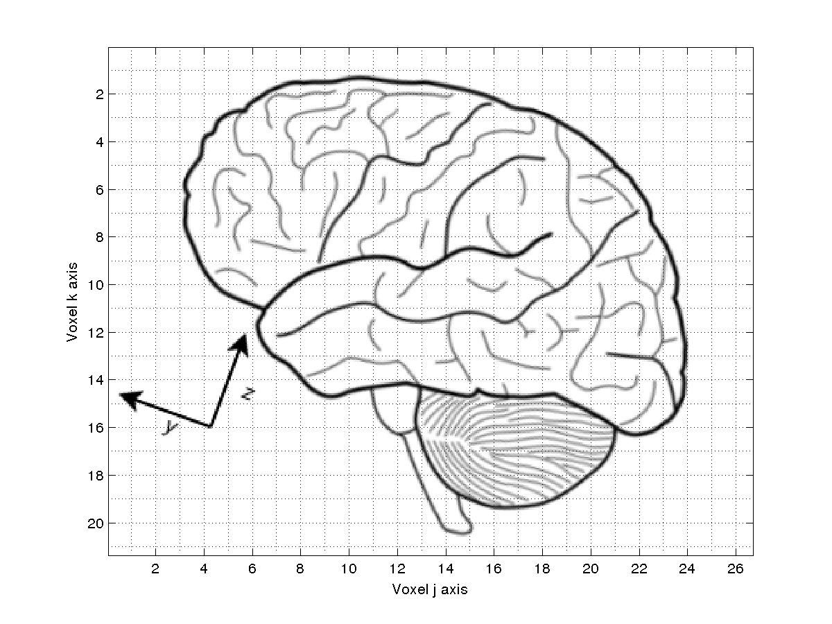
1.3 Coordinate system
Most medical image files can be thought of as having two different, but equally important coordinate systems. The
first system is called voxel coordinates in this document. By voxel coordinates we mean the position
of a particular voxel in the absolute reference frame of the sampled data. Since medical images are
generally sampled at discrete points in time and space, voxel coordinates are naturally also discrete,
and numbered from zero to Ni - 1 where Ni is the number of sample points along voxel dimension
i.
In contrast, world coordinates refer to the actual position of the patient with respect to the image. In
this document, we define that the world X-axis always increases from patient left to patient right, the
Y-axis increase from patient posterior to anterior, and the Z-axis increases from patient inferior to
superior.
Most medical image formats define a transformation from voxel coordinates to world coordinates. MNI Display
always defines a current cursor position within the space, and keeps of this position with respect to both coordinate
systems.
When displaying a single volume, MNI Display will show the volume oriented in its original voxel coordinate
frame, attempting to orient the image such that the voxel axis closest to the world X axis, for example, will be used
as the X axis in the image.
When displaying multiple volumes, MNI Display will re-orient subsequently loaded volumes so that their world
coordinates are consistent with those of the first loaded volume.
2 What’s new in Version 2.0
A number of major features have been added in MNI Display 2.0. Many of the features are cosmetic or user
interface improvements, others involve core functionality.
2.1 Core functions
- The intersection between a 3D surface and the loaded volume is automatically displayed in the slice
window.
- Dynamic scans (e.g. DTI, fMRI, and PET) can now be loaded in MNI Display.
- The ability to read FreeSurfer (.mgz/.mgh) and NIfTI-1 (.nii) volumes.
- Output support for surface formats including Wavefront OBJ, Stanford PLY, GIFTI, and X3D.
- Input support for surface and geometric formats including Wavefront OBJ, Stanford (.ply), GIFTI
(.gii), BrainSuite surfaces (.dfs), BrainSuite tractography (.dft), and FreeSurfer surfaces.
- The previous 20 painting operations can be undone.
- A user can now load per-vertex data, such as cortical thickness measurements, for visualization on 3D
surfaces.
- The ability to edit surfaces directly within MNI Display.
2.2 User interface
- Users can now save and restore their preferred window positions and sizes.
- Dynamic help text is displayed for each menu command.
- Better integration with modern mice and trackpads.
- Addition of new information in the 3D View and Slice View windows.
- New mouse and key bindings to speed access to important commands.
- User interaction can now use a graphical interface and dialog boxes rather than the terminal window.
- New layout and functionality in the object list window.
Each new version also includes many bug fixes and performance improvements.
3 Installing and Running MNI Display
MNI Display runs on most POSIX-compliant operating systems, including Linux and Mac OS X. You may find that
MNI Display is already installed on your workstation.
3.1 Installing MNI Display
If you do not already have MNI Display installed, you can install it as part of Minc Tools (version 1.0.01 is recommended),
following the instructions at: http://www.bic.mni.mcgill.ca/ServicesSoftware/ServicesSoftwareMincToolKit.
Alternatively, the source code for MNI-Display is available on Github: https://github.com/BIC-MNI/Display.
Once you have installed the program, you must also source the environment before you can run it. That is, if you
installed it to /opt/minc, then you must type in the terminal window:
source /opt/minc/minc-toolkit-config.sh # (for bash)
or
source /opt/minc/minc-toolkit-config.csh # (for tcsh)
Change these directories if it you installed the toolkit to a different location. Then you should be ready to run the
program.
More information about MNI-Display is also available at: http://www.bic.mni.mcgill.ca/software/Display/Display.html
and http://www.bic.mni.mcgill.ca/~david/.
3.2 Running MNI Display
To run MNI Display, type the following in a terminal window:
Display [file1] [file2] ... [fileN]
where each file is one of:
- A volumetric image, containing an MRI, PET, or other 3 or 4 dimensional volume, with a filename
extension .mnc, .nii, or .mgh.
- A 3D object file containing 3D surfaces, lines, or other objects, and with the filename extension
.obj (for MNI or Wavefront surfaces), .gii (GIFTI), .dfs (BrainSuite surface) .dft (BrainSuite
tractography), and .ply (Stanford PLY). A specific colour can be requested for the surface by
appending a colon (’:’) and the name of a colour to the file name
- A tag point file containing a list of 3D points, such as those chosen from a volume, with the filename
extension .tag.
- A colour map file that contains a list of label values followed by colour codes, with the file extension
.map.
Note that many of the above files may be compressed. If the file ends in .gz, then it is compressed and the full
name of the file, including the .gz, must be specified to MNI Display.
Note that you can load more than one of either the volumetric images or the 3D object files. If you do load
multiple files of the same type, they will be displayed in the appropriate window simultaneously. MNI Display will
attempt to overlay the two images, as long as they are in approximately the same location relative to the world
coordinate space.
Command line options to MNI Display are keywords introduced with a dash (’-’) character, often with one or
more additional arguments. Supported options include:
- -help : Print basic usage information and exit.
- -version : Print program and library version information and exit.
- -label filename : Load volume labels from the given file in .mnc or .tag format.
- -skiperror : Ignore errors encountered when loading files from the command line.
- -ratio V1,V2 : Display the value of volume number V1 divided by value of volume number V2 as
part of the slice window status. You must load at least two volumes for this option to have any effect.
- -global name value : Set the configuration variable of the given name to the specified value.
MNI Display supports an extremely large number of configuration options, many of these are
described in Appendix B.
- Initial range options: These options request MNI Display to use different approaches to setting the initial
range of the colour mapping used to convert voxel values into colours. They each set two values, Mmin and
Mmax, that define this range. Voxel values less than Mmin are assigned the “under” colour, and voxels greater
than Mmax are assigned the “over” colour.
- -range Amin Amax : Set the initial range used to map volume data to colours to the absolute
values specified. The value Amin should be less than Amax.
- -rel_range Rmin Rmax : Set the initial range used to map volume data to colours to the relative
values specified as a fraction of the total data range, Mmin = Vmin + Rmin(Vmax - Vmin) where
(Vmin,Vmax) is the real range of the voxel data. For example, if Rmin = 0.2, Vmin = -1.0, and
Vmax = +1.0, then Mmin = -0.6.
- -hist_range Pmin Pmax : Set the initial range used to map volume data to colours to the
percentile values specified. For example, a Pmin value of 0.2 attempts to set Mmin such that 20%
of all voxels will have values below the colour coding range.
- Volume colour coding options: These options apply to the colour coding used to display volumetric data,
they have no effect on surfaces.
- -gray : Use grayscale colour map for subsequently loaded volumes.
- -hot : Use hot colour map for subsequently loaded volumes.
- -spectral : Use spectral colour map for subsequently loaded volumes.
- -red : Use red colour map for subsequently loaded volumes.
- -blue : Use blue colour map for subsequently loaded volumes.
- -green : Use green colour map for subsequently loaded volumes.
The colour mapping options normally apply to the volumes specified after the option, and these options can be
repeated to set different values for subsequently loaded volumes. For example:
Display -gray -rel_range 0.1 0.9 t1.mnc -spectral -range 0 1000 rs.mnc
would load the first volume with the gray colour map and the colour coding range set at 10% and 90% of the real
voxel range. The second volume would be loaded with the spectral colour map and absolute colour coding range set
to 0, 1000.
Note that the colour options for surfaces are different from those for volumes. To request a specific colour for a
loaded surface, simply give the colour name after the filename, separated by a colon:
Display -gray s005_t1.mnc s005_gray.obj:yellow s005_white.obj:cyan
This command line specifies that the volume will be shown using the grayscale colour map, while the first surface
will be yellow and the second cyan.
See Appendix C for a complete list of colour names that MNI Display recognizes.
4 MNI Display Windows
When MNI Display starts, it normally creates up to four different windows. Each window has a specialized
purpose.
- The 3D view window displays the 3D objects, such as surfaces, lines, and markers. If no 3D objects
are loaded, it may not be displayed.
- The slice window displays up to 4 views of slices through one or more volumes. If no volumes are
loaded, it may not be displayed.
- The menu window shows the current menu command options.
- The object list window shows a list of the currently loaded 3D objects.
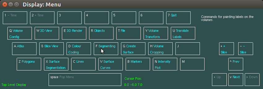
4.1 Menu Window
The menu window (Figure 2) contains the representation of the partial keyboard, the name of the currently
selected menu in the lower left corner.
The current cursor position (in world coordinates) is displayed in the lower central part of the menu window.
The cursor position will include the X, Y, Z, and time coordinates as appropriate.
As you move the mouse cursor over a key image displayed on the menu window, a brief text message describing
the function of that key will be displayed in the upper right corner of the menu window.
Any right mouse click on a key image will invoke the function associated with that key, if the key
image is not “grayed out”. The function associated with a key may either be a submenu or an actual
command.
A middle mouse click in the menu window will return the menu back up a level, similar to the operation of the
space bar.
This window always has the title “Display: Menu”.
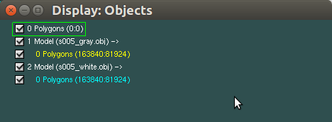
4.2 Object list window
All 3D objects loaded and created in MNI Display, with the exception of volumes, are listed in the object
hierarchy. The first entry in the object hierarchy list, which initially consists of the text ’0 Polygons(0:0)’, refers
to the built-in surface object used when surfaces are created in MNI Display.
The 3D objects used by MNI Display may be one of several types. They may be Markers that record a single 3D
position. They may be Polygons that represent a complex surface using a series of points or vertices to create a
triangular mesh. They may be Lines that represent a simple curve or shape, or a set of curves such as diffusion
tractography. Finally, Model objects act as containers for any number of other objects, including other
models.
The loaded objects are listed in the order they were given on the command line. Each loaded file is indicated by
a list entry that includes the word ’Model’ followed by the file name in parentheses, and an arrow. Loaded files are
always treated as model objects, which are objects that can contain other objects, including polygons.
You can explore the items contained in the model by using the arrow keys to navigate into the object
hierarchy.
The arrow keys are used to move around in this hierarchy and to select the current object. Also, clicking on an
object in the 3D view window or on the name of the object in the object list hierarchy with the left mouse button will
make it the current selection.
Objects that are created by the user, such as new markers or surfaces, will be added to the currently selected
model, and they will be added to the list in the object list window.
This window always has the title “Display: Objects”.
In the object list window, the following mouse operations are available:
- Left Button: If pressed over the object name, selects the named object to be the current object. If
pressed over the checkbox, toggles the visibility of the object.
- Shift+Left Button: If pressed over an object name, this command will allow the user to set the colour
of the selected object.
- Shift+Middle Button: Toggles the rendering mode of the object between shaded, wireframe overlay,
wireframe only, and point only mode.
- Right button: If pressed over a marker object, the cursor is immediately moved to the location of the
marker.
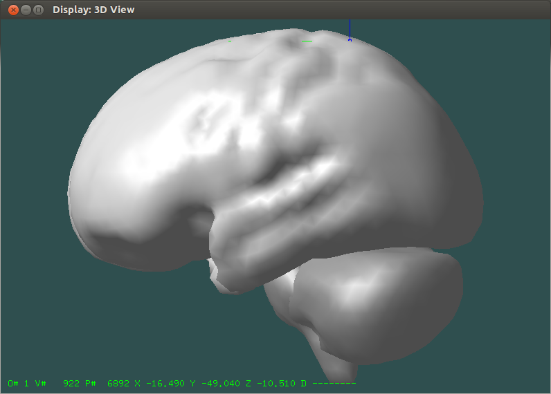
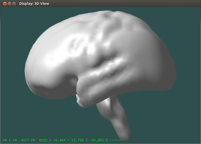
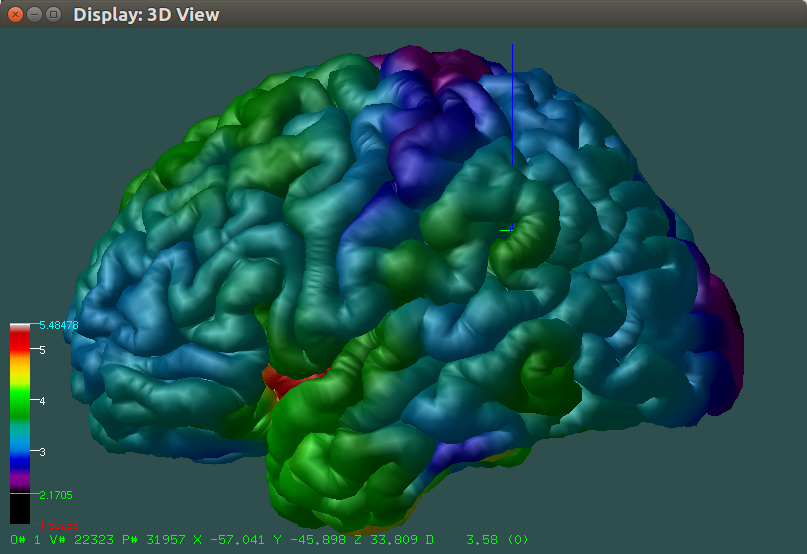
4.3 3D View Window
The 3D View window shows three-dimensional objects such as surfaces and lines, with lighting and camera
control. A representation of the cursor is also generally visible as a set of three coloured lines, where the X-axis is
red, the Y-axis is green, and the Z-axis is blue.
A user can also select per-vertex data, such as cortical thickness measurements, which may be
used to “colourize” the 3D image. If vertex data is associated with an 3D object, a colour bar will
be displayed on the lower left side of the 3D view window when the cursor crosshairs are over that
object.
In the 3D window, the following mouse operations are available:
- Left Button: Sets the current cursor position, and makes the object under the mouse the current object
in the Object list window.
- Middle Button: If the mouse is not near the cursor, rotates the 3D objects around the cursor. If the
mouse is close to the cursor, translates the cursor along the axes.
- Right button: translates the position of the 3D objects within the window.
- Scroll: zooms the 3D objects.
- Ctrl+Scroll: Changes the opacity of the selected object.
- Shift+Left Button: While holding down the shift key, the left mouse button translates the position
of the 3D objects within the window.
In addition, when per-vertex data is associated with an object and the object’s colour bar is therefore displayed,
the following mouse commands apply when the mouse cursor is in the colour bar:
- Left Button: If near the upper or lower limits of the colour bar, clicking the left button will allow you
to drag the limit and change the current upper or lower limits of the colour coding.
- Middle Button: Allows you to drag both limits simultaneously, maintaining a constant difference
between them.
- Shift+Left Button: Performs three different functions depending on exactly where the button is
clicked:
- In the area above the upper limit, this will display a dialog that allows you to set the “over”
colour for the object’s colour coding.
- In the area below the lower limit, this will display a dialog that allows you to set the “under”
colour for the object’s colour coding.
- In the area between the limits, this will display a dialog that allows you to set the colour coding
method used for this object.
The 3D window also contains a “status line” that gives information about the object relative to either the cursor
or the mouse pointer. The fields in this status line are enumerated in Table 1.
If the mouse pointer is over a 3D object, the status line displays the object number (relative to the list in the
Object list window), the vertex number, the polygon number, and the vertex coordinates closest to the mouse pointer.
If the mouse pointer is not over the 3D object, this information is displayed relative to the current cursor
position.
Table 1: Fields displayed in the status line of the 3D window.
| Label | Description |
|
|
| O# | The index (number) of the nearest object. |
| V# | The index of the nearest vertex. |
| P# | The index of the nearest polygonal face. |
| X Y Z | The coordinates of the nearest vertex. |
| D | The value of the per-vertex data for that vertex, if loaded. The number in parentheses
gives the data column that is currently displayed. |
|
|
| |
If per-vertex surface data is also loaded, that value associated with the current vertex will be displayed as
well. If no value is associated with the vertex, the value field will display as a series of eight dash
characters.
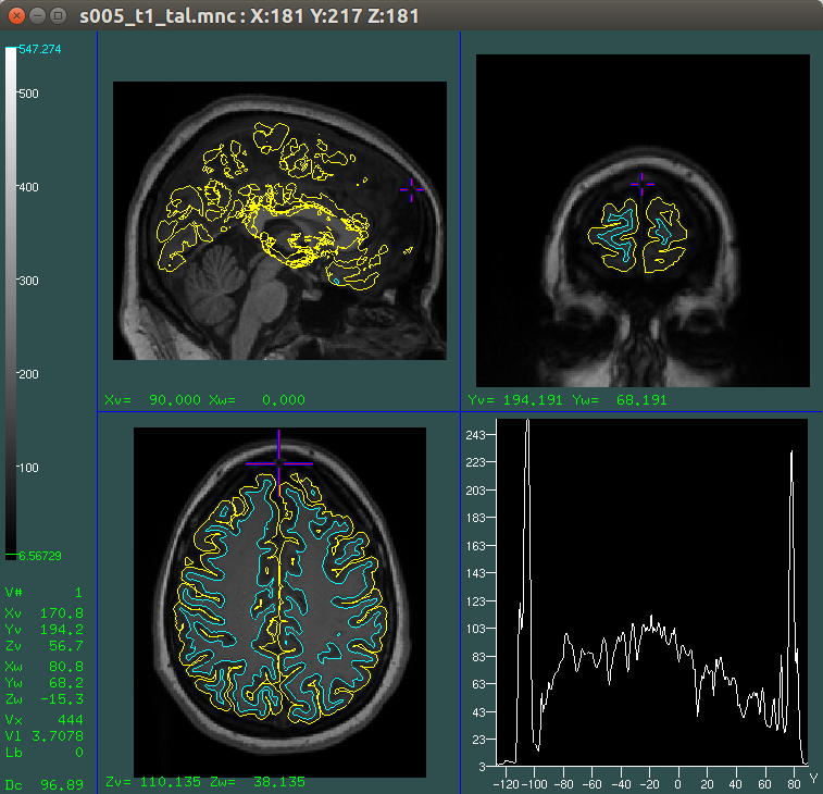
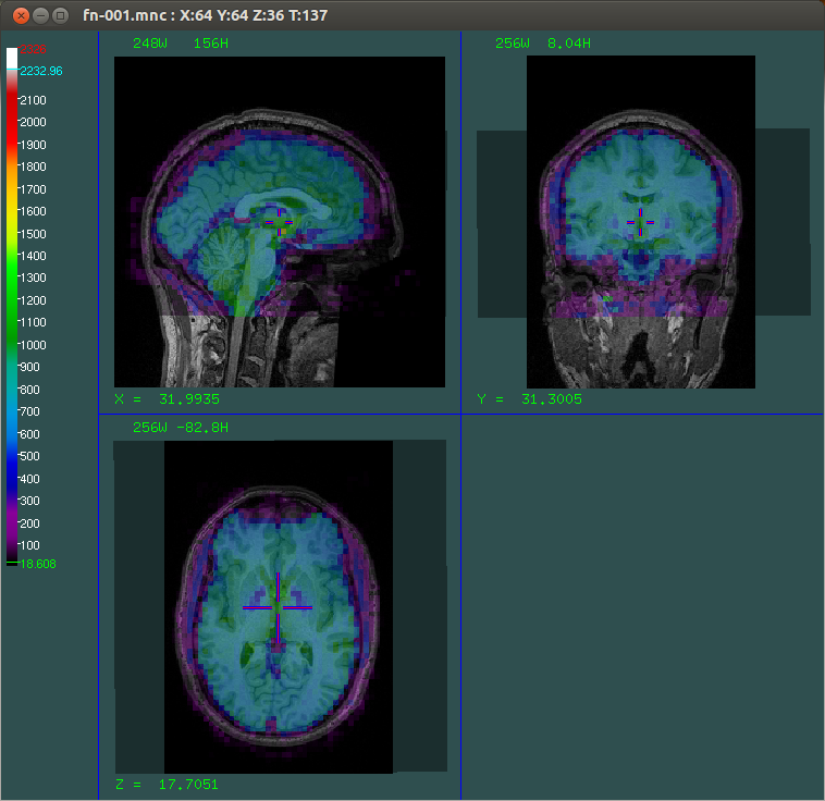
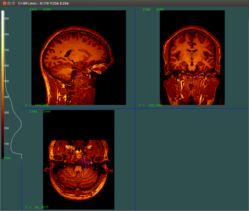
4.4 Slice Window
The slice window displays slices of the loaded volumes, with various options for mapping the voxel intensities
into colours. Normally the three orthogonal planes of a volumetric image will be displayed: The sagittal in the upper
left, the coronal in the upper right, and the transverse in the lower left. The lower right quadrant is generally used to
display either an intensity plot (Section 6.3) or an optional oblique slice through an arbitrary plane (Section
7.8).
In each of the three orthogonal quadrants, the width and height of the field-of-view is displayed in world units
near the top of the quadrant, and the current slice position in voxel coordinates is displayed near the bottom of the
quadrant.
The far left side of the window contains the colour bar that is used to show and control the current mapping of
voxel intensities to colours.
In the lower left corner there is also a numeric display that shows a number of useful value about the voxel under
the mouse pointer, as detailed in Table 2.
Table 2: Fields in the status display in the lower-left corner of the slice view window.
| Label | Description |
|
|
| V# | The index (number) of the current volume. |
| Xv Yv Zv | The location of the mouse pointer in voxel coordinates. |
| Xw Yw Zw | The location of the mouse pointer in world coordinates. |
| Vx | The raw voxel intensity. |
| Vl | The scaled voxel intensity. |
| Lb | The voxel label value. |
| n/m | The ratio between volume n and volume m, if enabled. |
| Dc | The distance from the cursor to the mouse pointer in world units. This field can also
show the distance from a marker to the mouse pointer, in which case the label will
show the number of the marker rather than the letter ’c’. |
|
|
| |
For each loaded volume, the slice window automatically associates another volume of the same size as the
loaded volume, which is referred to as the label volume. The label volume may be explicitly loaded by the user, but
if no such volume is loaded, an empty label volume will be created. Each voxel of the label volume typically is a
small integer value (in the range 0-255), where a value of zero means no label has been selected for this voxel. Each
label value is also associated with a colour. This colour mapping is initialized to a set of internal values
automatically, but you can load a specific colour mapping using either the command line or menu
system.
In other words, every loaded volume has one “voxel” colour map that is used for translating the values of the
original volumetric dataset into a set of colours, and there is a second “label” colour map used to translate each
user-assigned label value into a colour.
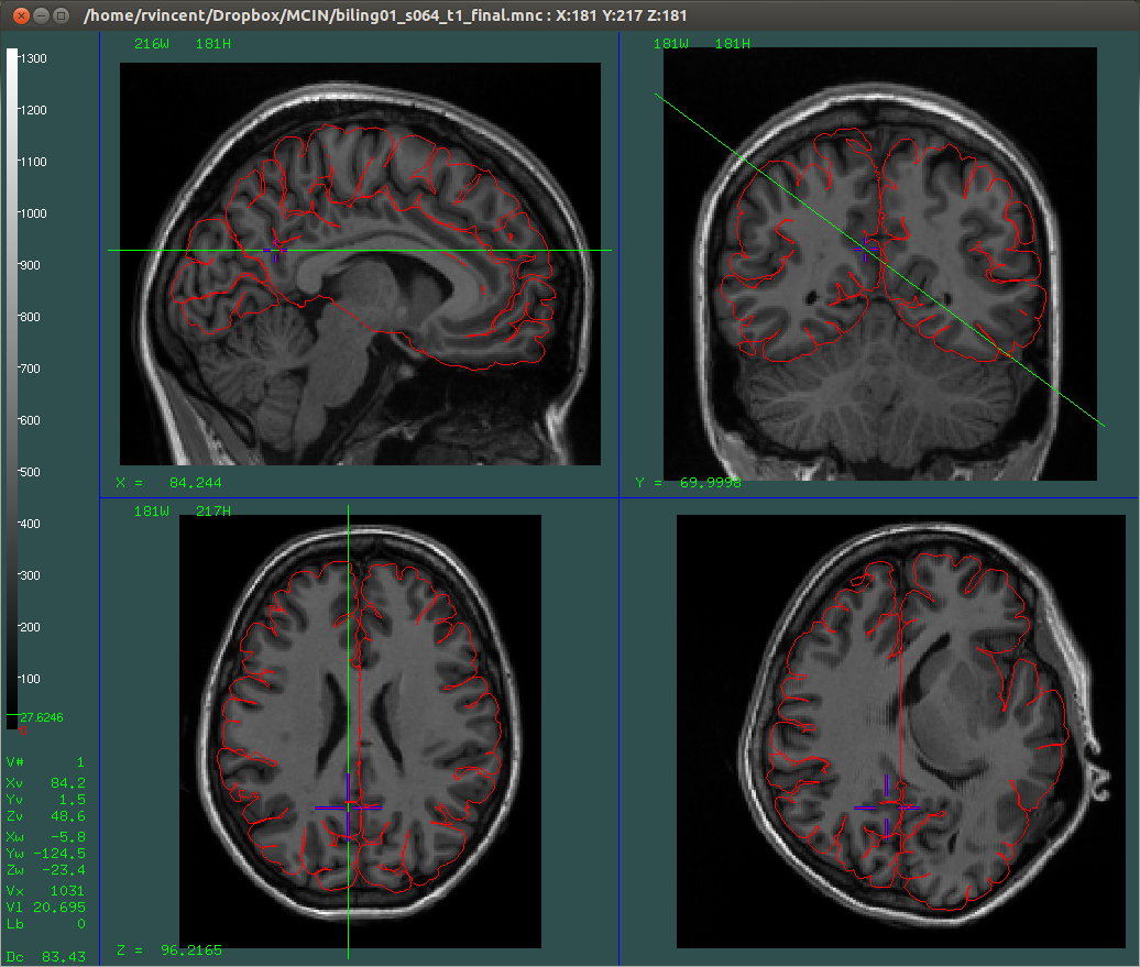
The slice window will also display a “trace” of any registered surface that is displayed in the 3D View
window. These traces represent the intersection between the surface and the plane in the current slice
view(s).
Multiple volumes can be overlaid on one another in the slice view. These volumes need not have the same
sampling grid, as long as they have the same position in world space. Each volume can have its own labels and
colour map.
In the slice window, the following mouse operations are available:
- Left Button: Sets the current cursor position.
- Middle Button: Moving the mouse up or down while holding down the middle button changes the
current volume slice position.
- Right Button: Paints a region of the current volume slice with the current brush label and size.
- Shift-Left Button: While holding down the shift key, the left mouse button translates the position of
the slice within the viewport.
- Shift-Middle Button: While holding down the shift key, holding down the middle button and moving
the mouse pointer up or down changes the magnification of the current slice.
- Shift-Right Button: While holding down the shift key, holding down the right button erases regions
of the labels.
- Scroll: The scroll wheel changes the zoom level of the current slice.
- Ctrl+Scroll: Changes the opacity of the selected volume.
- Ctrl+Left Button: Starts displaying a line measuring the distance between the start and end of the
mouse movement. There can be up to three of these line displayed at a given time. The intensity plot
will display the intensity along the most recently drawn line (the colour of the plot will reflect this).
In addition, the following mouse commands apply when the mouse cursor is in the colour bar:
- Left Button: If near the upper or lower limits of the colour bar, clicking the left button will allow you
to drag the limit and change the current upper or lower limits of the colour coding.
- Middle Button: Allows you to drag both limits simultaneously, maintaining a constant difference
between them.
- Shift+Left Button: Performs three different functions depending on exactly where the button is
clicked:
- In the area above the upper limit, this will display a dialog that allows you to set the “over”
colour for the volume’s colour coding.
- In the area below the lower limit, this will display a dialog that allows you to set the “under”
colour for the volume’s colour coding.
- In the area between the limits, this will display a dialog that allows you to set the colour coding
method used for this volume.
The relative sizes of the four slice views can be adjusted by clicking and dragging with the right button down
while the mouse cursor is close to the intersection of the dividing lines between the slices.
5 Menu and Interaction System
The menu window (Figure 2) represents the layout of the left side of the keyboard. A menu entry is selected by
hitting the corresponding key in any of the 4 MNI Display windows, or by pointing to the entry in the menu window
with the mouse and clicking the left button. The space bar will pop back one level in the menu (as will the middle
mouse button, when the mouse is over the menu window). If the display of a menu entry is “grayed out” (in a
low-contrast colour), then this signals that the command is not valid in the current context and cannot be
selected.
In the remainder of this document the following convention will be used to refer to menu selection:
3D View/Reset View means select the 3D View menu, then select the Reset View button from within the 3D View
menu.
Whenever text must be typed, such as in prompts for filenames, size and width parameters, etc., MNI Display
will attempt to display a subwindow or “dialog box” that prompts for the information requested. Each of these
dialog boxes contains an OK and Cancel button - selecting the Cancel button should always stop the requested
operation without changing anything.
Some menu items cannot be selected by the mouse because the mouse must be used to point to the object of the
action, usually one of the 4 volume slices in the slice window. In these cases, the mouse must be positioned over
the relevant slice in the slice window and the keyboard character corresponding to the menu entry
pressed.
Whenever the user is prompted to type in a colour, either the name of a colour, such as red, yellow, or pink, or
a numerical list of red-green-blue values, such as 0.3 0.7 0.7 (or 0.3 0.7 0.7 0.5 for a semitransparent
colour) may be entered. A complete listing of colour names support by MNI Display is given in Appendix
C.
5.1 Keyboard Shortcuts
MNI Display now supports a number of keyboard shortcuts for rapid access to certain commands. Many of these are
accessed by holding down the control (’Ctrl’) key and typing another key.
- Ctrl+B - Toggle between the primary and the secondary brush.
- Ctrl+O - Open a file (File/Load File).
- Ctrl+S - Save a file (File/Save File).
- Ctrl+V - Select the next column in multicolumn vertex data.
- Ctrl+Z - Undo the previous painting command (Segmenting/Undo).
- > - Move to the next time position (+ Time).
- < - Move to the previous time position (- Time).
- F10 - Toggle display of rulers in the slice view window.
- F12 - Toggle autorotation of the 3D objects.
6 Complete Menu Reference
The following is a complete listing of every menu selection, with a short description of each function. Since this
program is also partly a research tool, a few selections are not relevant to most users, and will simply be described as
not for general use. Figure 2 shows the top level menu that is presented upon program start up, or after popping the
menu to the top level.
6.1 Current Object
The 3D graphics objects, as displayed in the 3D window, are also presented in a hierarchical form in the object list
window, as a tree structure with each element of the tree being the name of a 3D graphics object. There are 4 keys
that can be used to navigate through the list, where the currently selected object is always displayed with a
surrounding box:
-
Prev
- Sets the current object to the previous item in the object list.
-
Next
- Sets the current object to the next item in the object list.
6.2 File
The file menu groups a number of commands relating to loading and saving file data of various types.
-
File/Load Labels .mnc
- Prompts for a filename and loads the file as the label volume for the current volume. The
label volume need not have the same sampling or extent as the volume on top of which it is being
loaded. This does not clear the current labels, unless the label file is exactly the same size and sampling
as the underlying volume.
-
File/Save Labels .mnc
- Prompts for a filename and saves the label volume of the current volume. The labels are
cropped to the smallest size possible.
-
File/Load Labels .tag
- Prompts for a filename and loads the tags file into the current label volume. Note that it
does not clear the current label volume, so the resulting labels are the union of the current labels and
the loaded tags. Also, it does not check that this is a valid label file, e.g., whether sizes match.
-
File/Save Labels .tag
- Prompts for a filename and saves the current label volume as a tag file. For large regions
this may create very large ASCII files, and it may be more efficient to save as .mnc.
-
File/Save Curr Lbl .tag
- Prompts for a filename and saves voxels with the current label to a tag file.
-
File/Load UserDef ColCode
- Prompts for a filename and loads the current user defined colour map as an ASCII
file, with a default suffix of .ccd. It automatically switches the colour coding mode to user defined, in
order to reflect the new map loaded from the file. Each line in file contains a position and a colour. The
first position in the file must be 0, the last must be 1, and the intermediate ones must be monotonically
increasing. The colours may be specified as 3 or 4 space separated values in the range 0 to 1, or as
one of the predefined colour names. For instance, the gray colour scale is equivalent to a file with two
lines, the first being 0 black, the second being 1 white.
-
File/Load Vertex Data
- Loads a file of per-vertex data, such as cortical thickness measurements, and associates it
with the currently selected object. The per-vertex data can be in most simple text formats, including
“vertstats” format.
-
File/Save Mrkrs as .tag
- Prompts for a filename and saves any markers at or under the current object to the file in
tag file format.
-
File/Save Slice Image
- If the mouse is pointing to one of the four slice viewports, prompts for a filename and
saves the contents of the slice viewport to the file, in .rgb format. This will work for the intensity plot
as well as the slice images.
-
File/Save File
- Prompts for a filename and saves the current object, or all objects contained in the current
object, if the current object is a model object. Files are typically saved in MNI .obj format, but single
polygonal surfaces can also be saved in Stanford (.ply), X3D (.x3d), or Wavefront (.wf.obj) format.
MNI Display will select the format based on the extension of the filename you supply.
This selection cannot be used to save a volume file.
-
File/Load File
- Prompts for a filename and loads the file. If it is a volume file (ends in .mnc), then the slice
window is opened, if not already opened.
-
File/Save Slice Window
- Prompts for a filename and saves the contents of the slice window to the file, in .rgb
format. Before doing this, make sure the window is up to date and not in the process of drawing.
-
File/Save 3D Window
- Prompts for a filename and saves the image contents of the 3D window to the file, in .rgb
format. Before doing this, make sure the window is up to date and not in the process of drawing.
-
File/Load Vertex Data
- If the currently selected object is a polygon, this command will load per-vertex data to
associate with this polygon. It will set the colours of the vertices appropriately, using the full range of
the data and the spectral colour map. The file is assumed to be a text file (extension .txt, .tsv, or
.csv), with exactly the same number of lines as there are vertices in the polygon.
-
File/Load Poly Visib.
- Not for general use.
-
File/Save Poly Visib.
- Not for general use.
-
File/Save Bintree
- Not for general use.
-
File/Load Bintree
- Not for general use.
-
File/Save Colour Map
- Prompts for a filename and saves the label colour map of the current volume as an ASCII
file, with a default suffix of .map. The label colour map is defined by Colour Coding/Set Paint Lbl Colour.
-
File/Load Colour Map
- Prompts for a filename and loads the current label colour map as an ASCII file, with a
default suffix of .map.
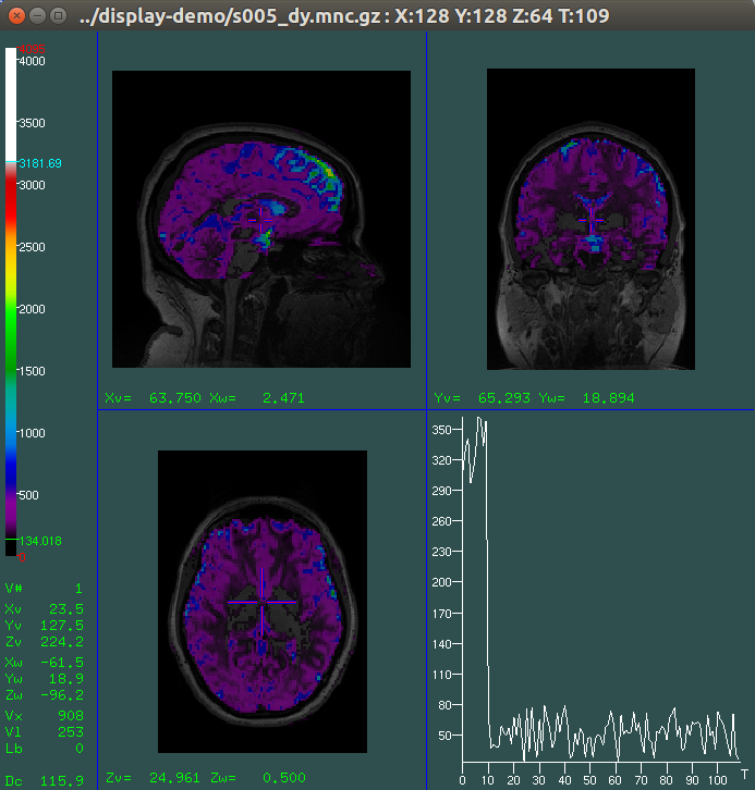
6.3 Intensity Plot
MNI Display can show a graph in the lower-right quadrant of the slice view window. This graph depicts the intensity
values along a line through the current cursor position, parallel to one of the spatial axes. If a time axis
is present, the intensity plot may also show the timecourse of the current cursor position or an ROI.
The Intensity Plot menu contains commands used to manipulate some of the options for displaying this
data.
By default, the intensity plot is enabled and the horizontal axis is selected automatically using the following
algorithm:
- If the current volume has a time dimension, the intensity of the current cursor location is plotted
through time.
- If a measurement line has just been drawn, the intensity plot is taken along that line.
- If the mouse is over the sagittal view, the intensity plot is taken along the Y (posterior-anterior) axis.
- If the mouse is over the coronal view, the intensity plot is taken through the Z (inferior-superior) axis.
- If the mouse is over the transverse view, the intensity plot is taken through the X (left-right) axis.
In each case, a letter ’X’, ’Y’, ’Z’, or ’T’ will be displayed on the horizontal plot axis to indicate which of the
axes is being used. If a measurement line is plotted, the horizontal axis simply shows the length in ’mm’ along the
line.
As explained above, when a time-varying (e.g. fMRI, DWI, or PET) image is loaded, the intensity plot will
automatically be computed using the time axis. Furthurmore, whenever the image is segmented, the labels will
be used to define regions of interest whose mean intensity will be plotted over the timecourse of the
ROI.
For example, if you load an fMRI image and wish to examine the timecourse of an specific region of interest,
first paint the ROI using the segmenting features of MNI Display. Then, move the cursor inside the ROI.
The intensity plot will change colour to reflect the colour of the ROI’s label. The intensity values will
be computed as the unweighted mean of all voxels with the selected label, for each time point in the
image.
When displaying a line along a spatial dimension, the background colour of the intensity plot will now reflect
the labeling of voxels along the line. This is intended to help guide labeling by showing changes in intensity
superimposed on the labels. The colours of the background will be immediately updated as changes are made to the
labeling.
In any case, the intensity plot will be automatically disabled whenever the oblique image is enabled.
-
Intensity Plot/Enabled: On
- Toggles the intensity plot on or off. If for some reason you do not wish to see intensity
plots, they can be disabled with this menu option.
-
Intensity Plot/Scaled: On
- If this option is on, the vertical axis of the intensity plot will be automatically scaled
to the actual data range of the currently selected data. If this option is off, the vertical axis will be
permanently set to the full range of the voxel intensities of this volume.
-
Intensity Plot/Axis: Auto
- This option allows to you specify a preferred choice for the horizontal axis in the
intensity plot. This command allows you to cycle through the choices Auto, X, Y, and Z. The time
dimension, T, is also available for time-varying scans. The Auto mode uses the logic described above
to set the horizontal axis based on the dimensions of the loaded volume and the position of the mouse
cursor.
If one of the specific axes is selected, that axis will be used as the horizontal axis in the intensity plot
irrespective of the current location of the mouse cursor. However, if a measurement line is drawn, the
intensity along that line will still be displayed on the intensity plot axis.
6.4 Quit
The Quit menu’s main function is to allow users to explicitly confirm their intention to quit MNI Display. However,
the menu includes a few miscellaneous commands.
-
Quit/Really Quit
- Select this if you are sure you want to exit MNI Display. The program will close.
-
Quit/Don’t Quit
- Select this if you do not want to quit MNI Display. You can also just press the space bar to
return to the previous menu.
-
Quit/Show Memory
- This command is intended for development and debugging purposes. It prints some possibly
useful information about the memory usage of MNI Display.
-
Quit/Global Var
- This command allows you to inspect or set the value of any of the many global variables
(configuration options) that are supported in MNI Display. When you choose this command, it will
prompt you to enter a string. The string can either be the name of a global variable, or a global variable
name followed by an equals sign and a new value. In the former case, the command will print the
current value of the global variable. In the latter case, the command will set the current value of the
global variable.
For a list of many of the useful global variables in MNI Display, see Appendix B.
-
Quit/Save Layout
- This command will save the current locations and sizes of all four windows (Menu, Slice
View, Object List, and 3D View). The saved information will be used to restore the window layout
the next time MNI Display is used. The information is saved in your home directory in a file named
.mni-displayrc.
6.5 Slice View
The slice view menu is primarily concerned with manipulating the orientation and position of the
three (or four) slice views. It also allows you to select which of the volumes is the currently active
volume.
-
+ Slice
- Moves the cursor to the next slice.
-
- Slice
- Moves the cursor to the previous slice.
-
+ Time
- Moves to the next time point in a dynamic scan.
-
- Time
- Moves to the previous time point in a dynamic scan.
-
Slice View/Curr Volume
- If more than one volume is loaded, then this button increases the current volume index.
If the the last volume is currently selected, this will return to the index of the first volume. The current
volume index is displayed in the lower left corner of the slice view, with the field title V#. For many
operations, including intensity plots and colour-coding selection, the current volume is used as the
target volume.
-
Slice View/Prev Volume
- If more than one volume is loaded, then this button decreases the current volume index.
If this command is chosen when the first volume is selected, the current volume index will be set to
the last volume loaded.
-
Slice View/Reset Slice View
- If the mouse is in the slice view window and is pointing to one of the 4 slices, then
the view for that slice is reset and resized to fit the viewport.
-
Slice View/Toggle Slice Visibility
- If the mouse is in the slice window and is pointing to one of the 4 slices, then the
visibility of that slice for the current volume is toggled.
-
Slice View/Box Filter Volume
- Prompts for 3 box filter widths and another specifier. If the specifier is the character
“w”, then the filter widths are assumed to be in world coordinates, otherwise it is assumed to be
voxel coordinates. The current volume is resampled using a box filter, creating new volume which is
overlaid on the original volume.
-
Slice View/Resample Volume
- Prompts for 3 size parameter and resamples the current volume to the given size,
creating another volume. Creates a volume with a smaller number of voxels by box filtering. It is
preferable to use Slice/Box Filter Volume, which maintains the number of voxels.
-
Slice View/Create 3D Slice
- Creates and displays a flat, colourized rendering of the slice pointed to by the mouse
in the 3D window.
-
Slice View/Create 3D Profile
- Creates and displays a 3D object surface reflecting the relative intensities of the
voxels in the current slice.
-
Slice View/Recompute Histogram
- Creates a histogram of values in the current volume, which is displayed in the
slice view window near the colour coding bar. If the mouse is pointing to a slice in the slice view
window, then the histogram of only that slice of the current volume is displayed.
-
Slice View/Histogram of Label
- Same as Slice View/Recompute Histogram, but only includes values which are in labeled
(segmented) regions.
-
Slice View/Toggle Plane Visibility
- This menu selection toggles the visibility of the cross section plane in the 3D
View window.
-
Slice View/Set Current Arb. View
- Each of the four slices can be oriented to an arbitrary angle. By pointing to one
of the slices and selecting this menu option, the user can set the current arbitrary view, which is the
one that the following slicing commands operate on.
-
Slice View/Toggle Slice Crs-Sect
- Turns on or off the visibility of the cross-section plane in the three views which
are not the current arbitrary view.
-
Slice View/Rotate Slice
- After selecting this entry, the middle mouse button in the 3D window will control rotation
of the arbitrarily oriented slice, updating the current view slice in the slice window.
-
Slice View/Pick Slice Angle
- Instead of rotating the slice in the 3D window, the orientation of the current view slice
can be chosen from within the slice window. After selecting this command, the left mouse button
selects a position on one of the other slices. The line through the slice cursor and this position is used
to define the slice plane of the current view slice.
-
Slice View/Toggle Slice Anchor
- Turns on and off the anchoring of the current view slice to pass through the cross
section of the current slice view. This is used to constrain a slice plane to pass through a given vector.
-
Slice View/Print Origin
- Prints the cursor location in world space in the terminal window.
-
Slice View/Print Plane Normal
- Prints the world space normal of the slice currently under the mouse.
-
Slice View/Type In Origin
- Prompts the user to type in a world space x, y, and z, and moves the cursor to this point.
-
Slice View/Type In Plane Normal
- If the mouse is pointing to one of the four slices, prompts the user to type in a
world space x, y, and z, and orients the slice plane to this normal.
-
Slice View/Visible:
- Makes only one volume visible, cycling through all loaded volumes as the button is pressed.
Whichever volume is made visible is set to the current volume.
-
Slice View/Make All Visible
- Make all of the volumes visible again.
-
Slice View/Vol Opacity:
- Prompts the user for an opacity value and sets the opacity of the current volume.
6.6 Volume Config
This menu includes several miscellaneous commands, as well as two sets of options for controlling the filtering or
smoothing of data in the Slice View window.
The global interpolation command, Volume Config/Interp:, changes the interpolation method used for all volume
accesses. As such, it will change both the volume display and the specific values shown in the Slice View status.
This interpolation smooths across all of the dimensions of the volume.
The per-view interpolation methods only affect individual views (the sagittal, coronal, or transverse planes). This
interpolation occurs only between slices, perpendicular to the slice view plane. The filter width setting controls how
many slices will be included in the filtered display.
-
Volume Config/Nearest Neighbour
- Sets the filter type of the current volume slice under the mouse to nearest
neighbour (this is the default).
-
Volume Config/Linear Int Filter
- Sets the filter type of the current volume slice under the mouse to linear
interpolation between the two nearest slices.
-
Volume Config/Box Filter
- Sets the per-view filter type of the volume slice under the mouse to a box filter. If the
mouse is not over a slice view, this command has no effect.
-
Volume Config/Triangle Filter
- Sets the per-view filter type of the volume slice under the mouse to a triangle filter.
If the mouse is not over a slice view, this command has no effect.
-
Volume Config/Gaussian Filter
- Sets the per-view filter type of the volume slice under the mouse to a Gaussian
filter. If the mouse is not over a slice view, this command has no effect.
-
Volume Config/Filter Width
- Prompts the user for the full width half maximum for the per-view filter of the slice
view under the mouse. Each view has its own filter width. This value applies only to box, triangle, or
Gaussian filters. It does not apply to the nearest-neighbour or linear filters. If the mouse is not over a
slice view, this command has no effect.
-
Volume Config/Interp:
- Toggles the global interpolation method used for rendering slice images for the entire
volume. The choices are nearest neighbour (the default), trilinear, and tricubic. This setting will affect
the values shown in the Slice View status display, as they will also be interpolated.
-
Volume Config/Delete Volume
- Brings up a submenu that allows the user to delete the current volume. This does
not affect the file from which the volume was loaded, it merely removes the volume from memory.
-
Volume Config/Share Labels
- Toggles whether or not segmenting labels are shared across volumes with identical
sampling. If this option is Off, each loaded volume is associated with its own independent label
volume. If this option is On, the default, a single label volume will be shared between all volumes with
identical sampling grids. Sharing labels allows users can paint a single set of labels on several similar
volumes, such as T1 and T2 volumes of the same patient.
-
Volume Config/Increm Update:
- Toggles the incremental update mode of the slice window. When it is on, the slice
window incrementally updates the slice window. This may still be useful when the slice window takes
a long time to update, such as with cached volumes or in trilinear interpolation mode.
6.7 Volume Cropping
This menu allows the user to specify a subregion of a volume and to create new volumes that are cropped to this
region.
-
Volume Cropping/Visibility:
- Toggles the visibility of the volume crop box in the slice planes. Note that the
position of the volume crop box is relative to the current volume, so changing the current volume will
change the appearance of the crop box.
-
Volume Cropping/Reset Crop Position
- Resets the volume crop box to the entire volume of the current volume.
-
Volume Cropping/Pick Crop Box
- After pressing this selection, an edge, a corner, or the entire crop box in the slice
window can be moved by pressing the left mouse button and dragging to the desired position.
-
Volume Cropping/Set Crop Source
- Prompts the user to type in the name of the file which will be cropped according
to the crop box.
-
Volume Cropping/Crop and Load
- Crops the current crop filename with the current crop box volume limits, and
loads the cropped file.
-
Volume Cropping/Crop to File
- Prompts for a filename and creates the cropped volume as this file, without loading
it.
6.8 Colour Coding
When you initially load a volume file, it will be displayed with the default HOT METAL (red-yellow)
colour coding. Use this menu to switch to other colour coding scales, or to set colour values for labeled
voxels.
-
Colour Coding/Spectral
- Selects the spectral colour coding method for the current volume.
-
Colour Coding/Gray Scale
- Selects the gray scale colour coding method for the current volume.
-
Colour Coding/Hot Metal
- Selects the hot metal colour coding method for the current volume.
-
Colour Coding/Red
- Selects the red colour coding method for the current volume.
-
Colour Coding/Green
- Selects the green colour coding method for the current volume.
-
Colour Coding/Blue
- Selects the blue colour coding method for the current volume.
-
Colour Coding/Arb Colour (Over)
- Selects the colour coding method for the current volume, where the scale ranges
from black through to the current over colour, which can be any valid colour.
-
Colour Coding/UserDef ColCode
- Selects the colour coding method for the current volume, where the scale is
defined by the user as any piecewise linear function. At present the only way to specify this function
is through the File/Load UserDef ColCode function.
-
Colour Coding/Contour
- Selects the rarely used contour colour coding method for the current volume.
-
Colour Coding/Range
- Prompts the user to type in the lower and upper colour coding limits for the current
volume. These may be the same, which results in a binary thresholded volume coloured by the under
and over colour. The upper limit may be a smaller number then the lower limit, which results in an
inverted colour map,
-
Colour Coding/Under Col
- Prompts the user to type in the colour for values in the current volume below the low
limit.
-
Colour Coding/Over Col
- Prompts the user to type in the colour for values in the current volume above the high
limit.
-
Colour Coding/Label Opacity
- Prompts the user to type in the intensity of the coloured labels superimposed on the
current volume slices. (0 <= value <= 1).
-
Colour Coding/Show Labels
- Toggles between showing or hiding the label volume superimposed on the current
volume.
-
Colour Coding/Set Paint Lbl Colour
- Prompts for a label value and a colour, and sets the displayed colour of this
label for the current volume.
-
Colour Coding/Num Labels
- Prompts for the number of labels desired, and recreates the current label volume with
this number. Depending on the number of labels, the volume may be a byte, short, or long valued
volume. Note that this effectively clears the current label volume.
-
Colour Coding/Colour Code Objects
- Changes the colours of the current object in the 3D window according to the
current colour coding parameters of the loaded volumes. This copies both the colours of any visible
volumes as well as their associated labels.
-
Colour Coding/Label Objects
- Changes the colours of the current object in the 3D window according to the current
colours of any visible labels, ignore the colours associated with the volumes.
6.9 Segmenting
This menu contains all the controls for modifying the current label volume, which is overlaid on the current volume.
For each voxel in the current volume, there is an associated integer value, which is stored in the current label
volume. Segmenting consists of painting regions of a label volume to change the values from the default of 0. When
the right mouse button is pressed over a slice in the slice window, the current paint label value is painted into the
label volume of the most recently loaded visible volume.
6.9.1 Erasing
The default value of all labels is zero, which is considered to be the “erased” value. The erased value can be changed
through the menu commands If the control key or shift key is held down along with the right mouse button,
erasing will be performed, by storing the value 0 (or the current erase value, if it has been set to something other
than zero).
6.9.2 Secondary brush
MNI Display implements a secondary brush size which can be quickly selected as an alternative to the
primary brush size. This allows rapid switching from fine-grained to coarse-grained painting. By default
the secondary brush is a sphere 3 units in diameter. The Ctrl+B key combination is used to toggle
between these brushes, and the menu commands to set the brush size will set the size of the current
brush.
-
Segmenting/Clear All Labels
- Sets all labels of the current volume to the erased state. Provides a cancel/confirm
submenu, but cannot be undone.
-
Segmenting/Set Paint Label
- Sets the current label used for painting. If the mouse is positioned over a voxel that
has a non-zero label when this menu command is selected, then the current paint value is copied from
that voxel. Otherwise, the user is prompted to type in an integer label, between 0 and one less than the
total number of labels.
-
Segmenting/Set Erase Label
- Sets the current label value used for erasing. If the mouse is positioned over a voxel
that has a non-zero label when this menu item is selected, then the current erase value is copied from
that voxel. Otherwise, the user is prompted to type in an integer label, between 0 and one less than the
total number of labels.
-
Segmenting/XY Radius
- Prompts for the in-slice brush radius (i.e. both the width and height) used in painting on
the volume slices. Any voxel which intersects the brush is painted. A radius of zero therefore paints
only voxel the mouse is in. This gives the finest control over painting.
-
Segmenting/Out-Plane Radius
- Prompts for the brush depth, the radius in the direction perpendicular to the slice
plane. This defaults to zero, for slice-by-slice painting. If this is non-zero, then a ellipsoidal brush
is used, and updating the display is a little slower because all slice views are updated as painting is
performed.
-
Segmenting/Undo
- Reverses the last painting or erasing operation which, in many cases, may be used to reset
the state of the labels to before the previous operation. Operations that affect many different slices,
such as loading labels from a file, or a 3D operation such as 3D fill, cannot generally be undone.
-
Segmenting/Label Voxel
- Sets the label of the voxel underneath the mouse to the current paint label. Can be
undone.
-
Segmenting/Clear Voxel
- Sets the label of the voxel underneath the mouse to the current erase label. Can be
undone.
-
Segmenting/Label Slice
- Sets the label of the entire slice pointed to by the mouse to the current paint label. Can
be undone.
-
Segmenting/Clear Slice
- Sets the label of the entire slice pointed to by the mouse to erase label. Can be undone.
-
Segmenting/Set Threshold
- Prompts for a minimum and maximum volume value, and uses these limits for
subsequent segmentation operations. When painting with the right mouse button, only voxels whose
values are within this range are affected. Operations such as dilation, erosion, and 2D and 3D filling
are also affected by the current threshold. By default, there is no segmenting threshold, which can be
explicitly specified, if desired, by a maximum value which is less than the minimum value.
-
Segmenting/Label Fill
- If the mouse is pointing to a voxel which is within the selected segmenting range and
which has a label not equal to the current paint label, then all similarly labeled voxels on this slice
connected to the starting voxel are assigned the current paint label, by a flood fill algorithm. Can be
undone.
-
Segmenting/Label Fill No Thrs
- Same as Segmenting/Label Fill, except ignoring the threshold. If the mouse is pointing
to a voxel has a label not equal to the current paint label, then all similarly labeled voxels on this slice
connected to the starting voxel are assigned the current paint label, by a flood fill algorithm.
-
Segmenting/Clear Fill
- If the mouse is pointing to a voxel which is within the selected segmenting range and
which has a nonzero label, then all similarly labeled voxels on this slice connected to the starting
voxel are assigned the erase label value, by a flood fill algorithm.
-
Segmenting/Connectivity
- Toggles between using 8 (or 26)-neighbour and 4 (or 6)-neighbour connectivity in 2D
(3D) operations such as fill, dilate, and erode.
-
Segmenting/Erode 3D
- Prompts the user for a label range which corresponds to outside the labels of interest, and
erodes regions of the current paint label which are neighbouring the typed-in label range. Typically
the user will type in “0 -1” to specify all labels which are not equal to the current paint label. Cannot
be undone.
-
Segmenting/Dilate 3D
- Prompts the user for a label range which corresponds to outside the labels of interest, and
dilates regions of the current paint label which are neighbouring the typed-in label range. Typically
the user will type in “0 -1” to specify all labels which are not equal to the current paint label. Cannot
be undone.
-
Segmenting/Copy from Rt/Sup/Ant
- If the mouse is pointing to a slice in the slice window, then the labels of the
neighbouring slice are copied to this slice. For transverse slices, the neighbour is the slice just superior
to this one. For coronal slices, the neighbour is the slice just anterior to this one. For sagittal slices,
the neighbour is the slice just to the right of this one. Can be undone.
-
Segmenting/Copy from Lt/Inf/Pos
- If the mouse is pointing to a slice in the slice window, then the labels of the
neighbouring slice are copied to this slice. For transverse slices, the neighbour is the slice just inferior
to this one. For coronal slices, the neighbour is the slice just posterior to this one. For sagittal slices,
the neighbour is the slice just to the left of this one. Can be undone.
-
Segmenting/Fill 3D
- If the mouse is pointing to a voxel which has a label which is not equal to the current paint
label and is within the threshold, then all similarly labeled voxels in the entire volume which are
connected to this one are assigned the current paint label. This may take a few seconds to a minute.
Cannot be undone.
-
Segmenting/Calculate Volume
- Calculates the total volume of all voxels which have the current paint label. This
may take few seconds to complete.
-
Segmenting/Change Labels
- Replaces a label, or a range of labels, with a new label value. Prompts for a source
label or label range, a destination label value, and as a volume value minimum and maximum value.
All voxels which have the source label value and are within the specified value range are changed to
have the destination label. If the maximum value specified is less than or equal to the minimum value,
then this range is ignored, and the operation simply changes all occurrences of the source label to the
destination label.
-
Segmenting/Fast Update
- Toggles between updating only the slice on which the mouse is painting or all slices, in
order to provide a speed tradeoff. By default, fast update is on, which results in fast painting.
-
Segmenting/Cursor Follows
- Toggles the mode where the slice cursor follows the mouse during painting. This
results in slower update speeds, but all slice views show updated labels as painting progresses, which
may be helpful for detail work.
-
Segmenting/Cursor Vis
- Toggles the visibility of the crosshairs cursor in the slice view window.
-
Segmenting/Freestyle
- Toggles freestyle painting, where the brush follows every movement of the mouse, and
straight-line painting, in which straight line segments are drawn between successive right mouse
clicks.
-
Segmenting/Enable Undo
- Toggles the state of the undo feature. Allows the undo logic to be enabled or disabled.
6.10 Translate Labels
This is a menu which may be used to translate position of the all labels by integral voxel increments.
-
Translate Labels/Trans ^
- Moves all labels one voxel in the upward direction of the slice pointed to by the mouse.
-
Translate Labels/Trans v
- Moves all labels one voxel in the downward direction of the slice pointed to by the
mouse.
-
Translate Labels/Trans <
- Moves all labels one voxel to the left direction of the slice pointed to by the mouse.
-
Translate Labels/Trans >
- Moves all labels one voxel in the right direction of the slice pointed to by the mouse.
-
Translate Labels/Big Translate
- Prompts for 3 voxel offsets and moves all labels by this amount.
6.11 Create Surface
This menu is used to create surfaces from the current volume and/or label volume. Surfaces created from this menu
may subsequently have their appearance smoothed by the use of Polygons/Compute Normals or Polygons/Average Normals.
During all surface extractions, the surface is displayed in the 3D window as it is being created, and all program
operations are still functional. Note that the currently set crop limits from the Volume Cropping menu are used to
constrain the range of the surface extraction.
-
Create Surface/Volume Isosurface
- Prompts for a value, then starts extracting a polygonal isosurface from near the
slice cursor, using a variation of the 3D contouring algorithm called marching cubes.
-
Create Surface/Volume Bin-Isosurf
- Prompts for two values, specifying a volume value range, then starts extracting
a polygonal isosurface from near the slice cursor. This differs from Create Surface/Volume Isosurface, in that
voxels are classified as in or out and the isosurface points are exactly half way between an inside voxel
and outside voxel. Typically, this is only useful for segmented volumes, otherwise the user should use
Create Surface/Volume Isosurface, which results in a smoother surface.
-
Create Surface/Volume Voxelate
- Prompts for two values, specifying a volume value range, then creates a voxelated
surface. A voxelated surface is one composed entirely of rectangular faces of voxels, the boundaries
between inside voxels and outside voxels, as defined by the value range specified.
-
Create Surface/Label Bin-Isosurf
- Same as Create Surface/Volume Bin-Isosurf except operates on the label volume. For
instance, if the user has painted a region with label 1, then to create a 3D isosurface of this region,
select this menu option, and type in “1 1” for the min and max values. Note that as the user paints and
erases labels, the 3D surface will update to reflect the changes.
-
Create Surface/Label Voxelate
- Same as Create Surface/Volume Voxelate except it operates on the label volume. For
instance, if the user has painted a region with label 1, then to create a 3D voxelated surface of this
region, select this menu option, and type in “1 1” for the min and max values.
-
Create Surface/Extracting
- If a surface extraction is in progress, this button toggles the extraction process on and
off. This allows suspension and resumption of surface extraction.
-
Create Surface/Reset Surface
- Cancels the current surface extraction, if any is in progress, deleting the extracting
surface. You must either make a created surface permanent, or reset the extracted surface, before you
can create another surface.
-
Create Surface/Make Permanent
- If a surface extraction is in progress, the currently extracted surface is made a
permanent member of the 3D object hierarchy, and the extraction terminated. You must either make a
created surface permanent, or reset the extracted surface, before you can create another surface.
-
Create Surface/Set Invalid Lbl Range
- Modifies the surface extraction so that any voxels with label values with the
specified range, which the user types in, are not used for the surface extraction. Defaults to the range
(0, -1), which indicates that no voxels are invalid.
6.12 Atlas
This menu controls the display of the Talairach atlas overlaid on the the slice views. The colour atlas book by
Talairach and Tournoux has been scanned into a digital format and can be overlaid on any volume for reference and
comparison purposes.
-
Atlas/Atlas State
- Toggles between displaying scanned images of the Talairach Atlas Book superimposed on the
volume slices. The first time this is pressed there will be a delay of about 2 minutes while the data is
read in.
-
Atlas/Set Opacity
- Prompts for the opacity of the atlas. A value of 1 will not show the volume slice through the
atlas, while values closer to 0 will show a more transparent atlas on top of the volume.
-
Atlas/Set Tolerance X
- Sets the distance from the current sagittal slice that atlas pages must be within in order to
be displayed.
-
Atlas/Set Tolerance Y
- Sets the distance from the current coronal slice that atlas pages must be within in order to
be displayed.
-
Atlas/Set Tolerance Z
- Sets the distance from the current transverse slice that atlas pages must be within in order
to be displayed.
-
Atlas/Flip X
- Flips the sagittal atlas pages around the X axis.
-
Atlas/Flip Y
- Flips the coronal atlas pages around the Y axis.
-
Atlas/Flip Z
- Flips the transverse atlas pages around the Z axis.
-
Atlas/Set Transparent Threshold
- Not for general use.
6.13 3D View
This menu allows for the rapid setting of the orientation and magnification of object in the 3D view window. It also
has some experimental features related to 3D rendering.
-
3D View/Front View
- Selects a view of the front of the objects.
-
3D View/Back View
- Selects a view of the back of the objects.
-
3D View/Left View
- Selects a view of the left side of the objects.
-
3D View/Right View
- Selects a view of the right side of the objects.
-
3D View/Top View
- Selects a view of the top side of the objects.
-
3D View/Bottom View
- Selects a view of the bottom side of the objects.
-
3D View/Left Tilted View
- Selects a view of the left side of the objects, tilted forward.
-
3D View/Right Tilted View
- Selects a view of the right side of the objects, tilted forward.
-
3D View/Reset View
- Resets the view to a top view.
-
3D View/Fit View
- Without changing the view direction, magnifies the objects to just fit inside the window.
Useful when the user desires to see the full extent of all objects.
-
3D View/Proj: Parallel/Perspective
- Toggles between a parallel and perspective view of the 3D objects.
-
3D View/Film Loop
- Creates a movie of the 3D window. Prompts for a filename prefix, an axis index (0-2), and
a number of frames. The objects are spun around the specified axis, saving a separate frame to file for
each increment.
-
3D View/Type-in Cursor Pos
- Prompts the user to enter the cursor position in world coordinates.
-
3D View/Print View
- Prints the current view parameters on the command-line terminal.
-
3D View/Front Plane
- Not for general use.
-
3D View/Back Plane
- Not for general use.
-
3D View/Toggle Stereo
- Not for general use. Stereo mode is not properly implemented.
-
3D View/Eye Width
- Not for general use.
-
3D View/Pick View
- Not for general use.
-
3D View/Set Persp Distance
- Not for general use.
-
3D View/Set Eye
- Not for general use.
-
3D View/Set Window Width
- Not for general use.
-
3D View/Set Line of Sight
- Not for general use.
-
3D View/Set Up Dir
- Not for general use.
6.14 Objects
This menu operates on the objects in the 3D window, which are also listed in the Object List window. The
object list is a hierarchical list consisting of lines, polygons, markers, and collections of these, called
models. Generally, object operations apply to the currently selected object which is the one which has a
green rectangle around its textual representation in the object list. Selection of the current object can be
performed by using the arrow keys to navigate the hierarchy, or by clicking on the desired object text in
the Object list window. Another way to select the current object is to click on its image in the 3D
window.
-
Objects/Delete Object
- Puts up a confirm/cancel submenu to allow the user to delete the current object. If the
current object is a model, the model and all objects it contains are deleted.
-
Objects/Change Colour
- Prompts for a new colour for the current object.
-
Objects/Change Surface Prop
- Prompts for an ambient coefficient (0–1), a diffuse coefficient (0–1), a specular
coefficient (0–1), a specular exponent (0–100 or so), and an opacity (near 0 is transparent, 1 is fully
opaque). The currently selected object is assigned these lighting parameters.
-
Objects/Invisible
- Turns the current object invisible.
-
Objects/Visible
- Turns the current object visible.
-
Objects/Toggle Visible
- Toggles the visibility of the current object.
-
Objects/Next Visible
- Turns the current object invisible, and advances to the next object, making it visible.
-
Objects/Prev Visible
- Turns the current object invisible, and advances to the previous object, making it visible.
-
Objects/Create Model
- Creates a model at the current position in the hierarchy. This is useful for grouping objects
into a single file.
-
Objects/Change Model Name
- Prompts for a name and assigns this to the currently selected model in the object
hierarchy.
-
Objects/Cut Object
- Cuts the currently selected object out of the object hierarchy and adds it to the cut buffer.
-
Objects/Paste Object
- Copies the entire cut buffer to the current position in the object hierarchy, and clears the
cut buffer.
-
Objects/Flip Object
- Mirror images the current object around the X = 0 plane.
-
Objects/Scan Object to Volume
- Causes the intersection of the current object with the volume to be displayed in the
slice window, by assigning the current paint label to any voxel which is touching the object. Works
for polygons, lines, and markers.
-
Objects/Show Vertices
- Creates a marker for every point on a surface. You probably don’t want to do this!
6.15 3D Render
This menu contains commands to changing the way 3D objects are displayed in the 3D view window.
-
3D Render/Change Background
- Prompts for a colour to set the background colour of the 3D window and slice
window.
-
3D Render/Mode: Shaded
- Toggles the display mode of the current model between a wireframe rendering, point
rendering, shaded (solid) rendering, and wireframe overlay (wireframe superimposed on shaded). The
default is shaded rendering.
-
3D Render/Shading: Gouraud or Flat
- Toggles the display mode of the current object between a flat or smooth
shading. The default is smooth (Gouraud).
-
3D Render/Lights: On or Off
- Toggles the lights on and off. If lights are off, all objects are coloured uniformly.
-
3D Render/2 Sided
- Not for general use.
-
3D Render/Backface
- Not for general use.
-
3D Render/Set # Curve Segments
- Not for general use.
-
3D Render/Marker Labels: Off or On
- Toggles the display of the text labels of the markers in the 3D window.
-
3D Render/Lines as Curves: Off or On
- Toggles whether lines are drawn straight or curved. May not be supported on
OpenGL.
6.16 Markers
This menu contains commands for creating and manipulating markers. Markers are graphical objects that define a
specific point in the volume. Each marker can be associated with a number of pieces of metadata, such as a label, a
colour, a structure ID, and a patient ID.
Markers are now displayed both in the slice view and the 3D view window. Markers will appear as outlines
superimposed on the slice view, or as 3D shaded objects in the 3D view. You can disable the display of markers in
the slice view by setting the global variable Show_markers_on_slice. Individual markers can be turned on or off
using the the Objects/Toggle Visible command.
-
Markers/Create Marker
- If the mouse is in the slice window over a volume pixel, a marker is created at that
location. Otherwise, it is created at the current cursor position.
-
Markers/Chg Marker Pos
- If the current object is a marker, then changes the marker’s position in a manner similar
to Markers/Create Marker.
-
Markers/Default Size
- Prompts the user to type in the default marker size in real world units, typically
millimetres.
-
Markers/Default Label
- Prompts the user to type in the default marker label string.
-
Markers/Default Colour
- Prompts the user to type in the default marker colour.
-
Markers/Default Structure Id
- Prompts the user to type in the default structure id.
-
Markers/Default Patient Id
- Prompts the user to type in the default patient id.
-
Markers/Default Type
- Toggles the current default marker type between cube and sphere.
-
Markers/Chg Marker Size
- Prompts the user to type in the new size of the current marker, if the current object is
a marker.
-
Markers/Chg Marker Label
- Prompts the user to type in the new label of the current marker, if the current object
is a marker.
-
Markers/Chg Marker Type
- Toggles the current marker’s type between cube and sphere, if the current object is a
marker.
-
Markers/Chg Marker Colour
- Prompts the user to type in the new colour of the current marker, if the current object
is a marker.
-
Markers/Chg Structure Id
- Prompts the user to type in a structure id. If the current object is a marker, then it is
assigned this structure id. If the current object is a model, then all markers underneath this object are
assigned this structure id.
-
Markers/Chg Patient Id
- Prompts the user to type in a patient id. If the current object is a marker, then it is
assigned this patient id. If the current object is a model, then all markers underneath this object are
assigned this patient id.
-
Markers/Move to Marker
- If the current object is a marker, sets the 3D cursor and the volume position to the
position of the marker.
-
Markers/Move Cursor Home
- Moves the 3D cursor to the origin, which should be 0, 0, 0 in Talairach space. This
is useful for making slides with the cursor as a reference to AC-PC.
-
Markers/Delete Object
- This is the same as the Objects/Delete Object, duplicated in this menu for convenience.
-
Markers/Defaults -> Current
- Copies the default marker values to the current object, if it is a marker.
-
Markers/Defaults -> Many
- Copies the default marker values to all markers which have the same patient id and
structure id as the current object, if it is a marker.
6.17 Polygons
This menu contains commands for creating and manipulating polygonal objects. These are used to define
surfaces.
Surface-based editing have recently been added to MNI Display. In this mode, the user can stretch
and deform a surface in 3-D to take a new shape. It is a very efficient way of correcting voxel-based
annotations that define a 3-D surface, as an opposed to correcting the voxel-based labels in each of the 3
planes.
The surface is loaded in MNI Display together with the volume and possibly labels. After editions, the modified
surface must be saved using File/Save File.
-
Polygons/Print Surface Area
- Computes and prints the surface area of the currently selected polygonal object.
-
Polygons/Set Line Thickness
- Prompts for a line thickness value used in displaying the current polygons in
wireframe mode. Default value is 1.
-
Polygons/Make Quad Ellipsoid
- Same as Polygons/Make Tetrahedral Ellipsoid except that the resulting polygons consist of
triangles and quadrilaterals defined by lines of longitude and latitude, and rather than specifying the
number of items composing it, the user specifies the number of intervals around and up the ellipsoid.
-
Polygons/Subdivide Polygons
- Not for general use.
-
Polygons/Create Bintree
- Not for general use. Creates a “bintree”, similar to a KD-tree, that can speed up certain
operations on polygons.
-
Polygons/Compute Normals
- Computes normals for the current polygon, for use in displaying a smooth lighted
surface in the 3D window.
-
Polygons/Reverse Polygons
- Not for general use.
-
Polygons/Reverse Normals
- Not for general use.
-
Polygons/Make Tetrahedral Ellipsoid
- Prompts for 3 numbers for the centre, 3 numbers for the radii, and an integer
for the number of triangles, and creates an triangulation of an ellipsoid. The resulting polygon is a
subdivision of a tetrahedron, an octohedron, or dodecahedron, depending on the number of triangles
specified, which will be rounded to an appropriate multiple of 4 times either 4, 8, or 20.
-
Polygons/Coalesce Polygons
- Causes individual polygons in the current polygons object to share common vertices,
which results in the object appearing to be more smoothly shaded.
-
Polygons/Separate Polygons
- Causes individual polygons in the current polygons object not to share common
vertices, which has the visual effect of causing the object to be flat shaded.
-
Polygons/Smooth Polygon
- Not for general use.
-
Polygons/Average Normals
- A second way to compute normals for a polygon, which results in smoother shading.
Prompts for a number of iterations and a ratio value between 0 and 1. The normals for the polygon are
computed using the Polygons/Compute Normals algorithm, then the iterations are performed. Each iteration
consists of smoothing each polygon vertex normal with its neighbour vertex normals, based on the
ratio value. A value of 0 causes no change in each iteration, where a value of 1 sets each vertex normal
to the average of its neighbour vertex normals. Typically, use the values “5 1” for this selection.
-
Polygons/Move Vertex
- Move a vertex and its surrounding neighbours on a triangulated mesh towards a
user-specified location pointed to by the last mouse click.
-
Polygons/Nearest Vertex
- Select the initial vertex around which the mesh will be moved.
-
Polygons/Smooth Around Vertex
- Perform geometric smoothing of the mesh around the selected vertex.
-
Polygons/Vector Surface Params
- Set the parameters for surface-based editing. The first parameter is the number of
levels of connected triangles around the selected vertex (default 10). The second parameter defines
a radius of action (in terms of a fwhm) around which the vertex and its neighbours are moved in a
smooth fashion (default 5 units in world coordinates).
6.18 Surface Curves
This menu is used to draw curves on surfaces, for the purposes of delineating sulci and gyri, or for drawing regions
on the surface which can then be coloured.
-
Surface Curves/Start Surf Curve
- Enters curve drawing mode. Any left mouse click on the surface in the 3D
window will define a point on the surface. Subsequent points on the surface are connected by a line
of shortest distance along the surface. The first mouse click will cause precomputation of neighbours
in the polygons which may take several seconds.
-
Surface Curves/End Surf Curve
- Exits from curve drawing mode.
-
Surface Curves/Close Curve
- When in curve drawing mode closes the curve by connecting the end of the curve
with the start of the curve.
-
Surface Curves/Pick Line Point
- Picks the closest point on a line to the point under the mouse, and adds it to the
current surface curve.
-
Surface Curves/Reset Curves
- Clears the current curve.
-
Surface Curves/Permanent Curve
- Copies the current curve permanently into the object hierarchy.
-
Surface Curves/Curve Weight
- Prompts the user to type in a curvature weight. A value of -100 will tend to make
surface curves follow sulci, and a value of 0 (default) makes it just choose shortest path along the
surface. Generally, this parameter has not been very successful, and it is best to leave it at 0.
-
Surface Curves/Set Crv’tre Limits
- Prompts the user for a minimum and maximum curvature and constrains
subsequent curves to follow paths along the surface to stay within these surface curvature limits.
Generally, this is not used.
6.19 Surface Segmentation
This menu is used for segmenting the a polygonal surface into various coloured regions or to make parts of the
surface invisible. Every face of a polygonal surface can be rendered invisible if the appropriate flag is cleared. To
assist with these operations, MNI Display defines two colours, the “visible” colour and the “invisible” colour.
Polygonal faces that have been marked with the current “invisible” colour may be hidden or removed from the
polygonal object.
Changes made to a polygonal surface may be saved by using the File/Save File command.
-
Surface Segmentation/Cut Neighbours
- TBD
-
Surface Segmentation/Invis Col -> Invis
- Finds each face that has been painted with the current invisible colour, and
actually makes that face invisible (transparent).
-
Surface Segmentation/Reset Visible
- Makes every face of the current polygonal surface visible and sets it to the
visible colour.
-
Surface Segmentation/Set Coloured Visible
- Makes every face of the current polygonal surface invisible if it is painted
with the current invisible colour. Otherwise the face is made visible.
-
Surface Segmentation/Remove Invisible
- Actually removes invisible faces from the polygonal surface.
-
Surface Segmentation/Crop Above
- Remove all faces that are entirely above the current X, Y, or Z plane. Prompts
for the plane to use.
-
Surface Segmentation/Crop Below
- Remove all faces that are entirely below the current X, Y, or Z plane. Prompts
for the plane to use.
-
Surface Segmentation/Reset Neighbours
- TBD
-
Surface Segmentation/Vis -> Invis Colour
- Sets every visible face such that it is also marked with the invisible colour.
-
Surface Segmentation/Vis -> Vis Colour
- Sets every visible face such that it is also marked with the visible colour.
-
Surface Segmentation/Paint Invisible
- Paints the group of faces near the mouse cursor with the invisible colour, and
makes them invisible. The numberof faces is determined by the current paint size.
-
Surface Segmentation/Paint Visible
- Paints the group of faces near the mouse cursor with the visible colour, and
makes them visible. The numberof faces is determined by the current paint size.
-
Surface Segmentation/Vis Col:
- Prompts the user to enter a new colour to use for the visible colour.
-
Surface Segmentation/Invis:
- Prompts the user to enter a new colour to use for the invisible colour.
-
Surface Segmentation/Connected Vis Colour
- Sets all connected polygonal faces to the current visible colour.
-
Surface Segmentation/Connected Invis Colour
- Sets all connected polygonal faces to the current invisible colour.
-
Surface Segmentation/Paint Vis Colour
- Paints the group of faces near the mouse cursor with the visible colour. The
number of faces is determined by the current paint size.
-
Surface Segmentation/Paint Invis Colour
- Paints the group of faces near the mouse cursor with the invisible colour.
The number of faces is determined by the current paint size.
-
Surface Segmentation/Paint size:
- Prompts the user to enter a new paint size, the number of polygons (faces) to
change on each paint operation.
6.20 Volume Transform
This menu contains commands that allow you to apply an arbitrary rigid body transform to a loaded volume. It also
contains a few useful commands related to volumes and the slice view.
-
Volume Transform/Prev Visible
- Select the previous volume and make it visible.
-
Volume Transform/Scale Down Volume
- Transform the volume by dividing its size by the current scale step.
-
Volume Transform/Scale Up Volume
- Transform the volume by multiplying its size by the current scale step.
-
Volume Transform/Insert Volume as Labels
- Insert a selected volume as the label volume of the currently selected
volume.
-
Volume Transform/Visible: 1
- Makes only one volume visible, cycling through all loaded volumes as the button is
pressed. Whichever volume is made visible is set to the current volume.
-
Volume Transform/Xform Volume Frm File
- Prompts the user for a transform file name, and then transforms the
current volume accordingly.
-
Volume Transform/Reset Vol Xform
- Resets the volume transform to its original state, that is, the transform specified
in the file itself.
-
Volume Transform/Trans Step: 1
- Prompts the user to enter a new value for the translation step, in world units.
-
Volume Transform/Rot Step: 1
- Prompts the user to enter a new value for the rotation step, in degrees.
-
Volume Transform/Save Volume Xform
- Prompts the user for a filename and saves the current volume transform as a
.xfm file.
-
Volume Transform/Scale Step: 1.05
- Prompts the user to enter a new value for the scale step, as a fraction of the
current size.
-
Volume Transform/Trans + X
- Translates the volume towards the positive X axis using the current translation step.
-
Volume Transform/Trans + Y
- Translates the volume towards the positive Y axis using the current translation step.
-
Volume Transform/Trans + Z
- Translates the volume towards the positive Z axis using the current translation step.
-
Volume Transform/Rot + X
- Rotates the volume clockwise around the X axis using the current rotation step.
-
Volume Transform/Rot + Y
- Rotates the volume clockwise around the Y axis using the current rotation step.
-
Volume Transform/Rot + Z
- Rotates the volume clockwise around the Z axis using the current rotation step.
-
Volume Transform/Trans - X
- Translates the volume towards the negative X axis using the current translation step.
-
Volume Transform/Trans - Y
- Translates the volume towards the negative Y axis using the current translation step.
-
Volume Transform/Trans - Z
- Translates the volume towards the negative Z axis using the current translation step.
-
Volume Transform/Rot - X
- Rotates the volume counterclockwise around the X axis using the current rotation
step.
-
Volume Transform/Rot - Y
- Rotates the volume counterclockwise around the Y axis using the current rotation
step.
-
Volume Transform/Rot - Z
- Rotates the volume counterclockwise around the Z axis using the current rotation step.
7 Step by Step Examples Using MNI Display
7.1 How to Change Colour Coding
To select a specific colour coding option, you can specify it on the command line:
Display -gray structural.mnc
This will load the given volume with the grayscale colour map instead of the default hot metal colour
map.
You can specify multiple colour-coding options on the command line. They will apply to each of the volumes
listed after the option. For example:
Display -gray t1-001.mnc -spectral fn-001.nii
will load t1-001.mnc and display it using the grayscale colour map, then load fn-001.mnc and display it using
the spectral colour map, overlaid on the T1 image (See Figure 7).
Once a volume has been loaded, you can change the colour coding of the current volume at any time by using
Colour Coding menu. You can select one of the other colour map options, such as Colour Coding/Spectral or
Colour Coding/Gray.
7.2 How to Create and Save Labels
- Start MNI Display the usual way, loading a volume:
Display prefix_104_t1_final.mnc
- The default paint label value is 1. To change this, click on Segmenting/Set Paint Label and then enter the number
corresponding to the colour of the paint label that you want associated with painting operations. See Table 3
for the default mapping of label values to colour names.
- The default brush radius in the plane is 3 world units. To change this, click on Segmenting/XY Radius and then
enter the desired size of the paint brush in world units.
- You can hold down the right mouse button to draw on the current volume using the current label value and
brush size, or you can use the Segmenting/Label Voxel command to set the voxel directly under the mouse
pointer.
- If you make a mistake in drawing labels, you can undo up to the last 20 painting operations using the
Segmenting/Undo command. You can also access this command with the Ctrl+Z key combination.
- When you wish to save the labels, you can use either the command File/Save Labels .mnc or File/Save Labels .tag. The
ASCII tag file format (.tag) may become overly large if you have defined many labels. The MINC (.mnc)
format will be more space-efficient in this case.
- Remember that you can zoom in and out to examine more or less detail in the slice by using the scroll wheel
or the shift key + middle mouse button.
Table 3: Table of standard label colour codes used in MNI Display. Only the first 25 entries are shown.
Entries from 14 and above are derived automatically from the label value and are not necessarily associated
with colour names.
| Label Value | Colour Name | Colour RGB |
|
|
|
| 1 | RED | 1.00 0.00 0.00 |
| 2 | GREEN | 0.00 1.00 0.00 |
| 3 | BLUE | 0.00 0.00 1.00 |
| 4 | CYAN | 0.00 1.00 1.00 |
| 5 | MAGENTA | 1.00 0.00 1.00 |
| 6 | YELLOW | 1.00 1.00 0.00 |
| 7 | BLUE_VIOLET | 0.54 0.17 0.89 |
| 8 | DEEP_PINK | 1.00 0.08 0.58 |
| 9 | GREEN_YELLOW | 0.68 1.00 0.18 |
| 10 | LIGHT_SEA_GREEN | 0.13 0.70 0.67 |
| 11 | MEDIUM_TURQUOISE | 0.28 0.82 0.8 |
| 12 | PURPLE | 0.63 0.13 0.94 |
| 13 | WHITE | 1.00 1.00 1.00 |
| 14 | | 0.40 0.00 0.00 |
| 15 | | 0.40 0.20 0.00 |
| 16 | | 0.40 0.40 0.00 |
| 17 | | 0.20 0.40 0.00 |
| 18 | | 0.00 0.40 0.00 |
| 19 | | 0.00 0.40 0.20 |
| 20 | | 0.00 0.40 0.40 |
| 21 | | 0.00 0.20 0.40 |
| 22 | | 0.00 0.00 0.40 |
| 23 | | 0.20 0.00 0.40 |
| 24 | | 0.40 0.00 0.40 |
| 25 | | 0.40 0.00 0.20 |
|
|
|
| |
7.3 How to Load Labels
When MNI Display starts from the command line, you can load labels by using the -label option and specifying
the desired .tag or .mnc file:
Display patient_t1.mnc -label patient_t1.tag
or
Display patient_t1.mnc -label patient_t1.mnc
If you prefer, you can load labels while MNI Display is already running by using either the File/Load Labels .tag or
File/Load Labels .mnc command as appropriate.
7.4 How to change one label value to another
The Segmenting/Change Labels command allows you to either change a single label to another value, or to erase all voxels
of a particular label. This is similar to a “global search and replace” feature. Because of the potentially large number
of changed voxels, this command cannot be undone!
To change one label to another, perform the following steps:
- Select the Segmenting/Change Labels command.
- When prompted for the “Label or range to change from”, enter the existing label value you want to
change and press OK.
- You will no be prompted for the “Label to change to:”. Enter the new label value and press OK.
- You will finally be prompted for the “Min and max of value range:”. You can just enter “0 0” here.
Press OK.
- MNI Display will now change all instances of the original label to the new label.
To restrict the change to apply only to voxels whose ranges are within a specific intensity threshold, you can
specify that range in step 4 above. If the second value is greater than the first, then only those voxels with values
lying within that interval will be affected by this command.
To erase a label, specify the label value zero (’0’) in step three above. The minimum/maximum range still
applies if specified.
7.5 How to Create a 3D Rendering of a Label
- Start MNI Display the usual way, loading the volume and labels:
Display prefix_104_t1_final.mnc -label prefix_104_labels.mnc
- Click somewhere on the part of the labeled volume that you want to render as a 3D surface.
- Go to the Create Surface menu.
- Select Create Surface/Label Bin-Isosurfac.
- Then, in the dialog window, type the MIN and MAX of the label - for example, if your value is 1, type 0.5
1.5.
- This performs a marching cubes rendering of the label in the objects window.
- If you want to save the extracted surface, you must use the Create Surface/Make Permanent command to copy the
surface into the object hierarchy before you can create another surface.
- Alternatively, you can delete the extracted surface and try again by selecting the Create Surface/Reset Surface
command.
- The extracted surface can then be smoothed using Polygons/Smooth Polygon.
You can smoo
7.6 How to Draw a Curve on the Cortical Surface
- Start MNI Display, loading a cortical surface:
Display prefix_104_gray_surface_left_81920.obj
- Select Surface Curves.
- Select Surface Curves/Start Surf Curve and click with left mouse button to start drawing curve on surface.
- Click again with left mouse button on next point on surface and keep clicking to add new points to
curve. Each time you click, it will connect the points using the line of shortest distance on the
surface.
- When done clicking points on surface, Surface Curves/Close Curve to finish and close the curve.
- When done drawing curves, select Surface Curves/End Surf Curve to stop drawing surface curves entirely.
- To save the curve, select Surface Curves/Permanent Curve, which will move the curve into the object hierarchy as a
lines object.
7.7 How to Crop a Volume
- Start MNI Displaywith your volume that you want to crop as input:
Display prefix_104_t1_final.mnc
- Select the Volume Cropping menu.
- Select the Volume Cropping/Set Crop Source and enter a file name (for example “prefix_104_t1_final.mnc”).
- Select the Volume Cropping/Pick Crop Box command.
- A green contour will appear around the slice planes. You can move the side of the crop window with your
mouse.
- Save the new cropped volume by pressing on Volume Cropping/Crop To File and enter a file name for the cropped
volume.
- You can now load the new cropped volume.
7.8 How to Display an Oblique Slice View
You can display an oblique (arbitrary) slice through the volume, as shown in Figure 8.
- Start MNI-Display as usual with a volume:
Display prefix_104_t1_final.mnc
- Select the Slice View menu.
- Move the mouse over the lower right quadrant of the slice view window.
- Select the Slice View/Toggle Slice Visibility command to make the fourth slice visible.
- Select the Slice View/Toggle Slice Crs-Sect command to display slice cross section. This will display a green line
which shows the intersection of the oblique plane with the current slices.
- Select the Slice View/Pick Slice Angle command to allow you to use the left mouse button to change the angle of the
oblique slice in any of the three orthogonal views.
7.9 How to Display Functional Activation on a Volume
This can be done by loading both the functional volume (i.e. PET) and the anatomical cortex object. For example,
type the following:
Display pet_volume.mnc cortex.obj
Then perform the following steps:
- Select Colour Coding/Under Colour and set the colour to white or 0.7 0.7 0.7.
- Select the command Colour Coding/Colour Code Object.
Note that this procedure applies the current colour coding parameters to the current object, and after you make
any change to colour coding parameters, you have to hit the Colour Coding/Colour Code Object button to cause the 3D
object to be updated.
7.10 How to Load Several Objects and Switch Between Them
- Type the following to load an average model brain and models of brainstem and cerebellum:
Display ti_final.mnc avg_model.obj brain_stem_model.obj cerebellum_model.obj
- Initially the 3D window displays the average model as well as the brainstem and cerebellum, as in Figure 9
(use 3D View/Left View to display a side view).
- Note that the cerebellum object, the final object loaded, is the currently selected object in the Object list
window.
- Select the Objects/Previous Visible command, and the cerebellum object will no longer be displayed. The current
object will now be the brain stem object, as in Figure 10.
- Select the command Objects/Previous Visible again, and the brain stem object will be hidden as well.
- You can use the arrow keys and Objects/Visible or Objects/Invisible commands to select any object and change its
visibility.
- Invisible objects are not shown in either the 3D view or the slice view.
7.11 How to Create a Cut-Away View of a Cortical Surface
Within MNI-Display you can create a cut-away view of the cortical surface to show anatomical features inside. Type
the following to open an average model brain and model of brainstem and cerebellum:
Display ti_final.mnc avg_model.obj brain_stem_model.obj cerebellum_model.obj
- Rotate the 3D model, using either the 3D View menu or the middle mouse button, until you have the
desired viewing angle.
- Select the polygon object you want to crop. You may select an object either by using the arrow keys
or by clicking the mouse over the object in the 3D View.
- In the Slice View window, navigate to the slice coordinate in the view where you want to cut the
object.
- Press the key corresponding to the Surface Segmentation/Crop Above or Surface Segmentation/Crop Below
command while your mouse is still over the sagittal, coronal, or transverse slice.
- The cropped part of the polygon object will disappear.
7.12 How to Display a Histogram of Voxel Intensities
The Slice View window can show a graph giving a visual indication of the relative frequencies of different voxel
values.
- Start MNI Display as usual, opening a volume:
Display ti_final.mnc
- Select the command Slice View/Recompute Histogram. This will show a histogram of voxel intensities next to the
colour bar scale.
- If the mouse is over a particular slice when the command is selected, the histogram will reflect the intensities
of that slice only. Otherwise, the histogram will be taken over the entire volume.
- You have to explicitly choose the Slice View/Recompute Histogram command to update the histogram.
7.13 How to Create a Cortical Surface from a Volume
- Start MNI Display as usual, opening a volume:
Display prefix_104_ti_final.mnc
- Switch to Colour Coding/Gray Scale.
- Select the Create Surface menu.
- Move mouse on volume to position where surface extraction should start.
- Select the Create Surface/Volume Isosurface command
- Type isovalue into Text Input window (e.g. 140).
- The surface will be extracted and will appear in 3D window. This operation can take some time.
- If the surface extraction does not work properly, you can select Create Surface/Reset Surface to remove the
existing surface and try again with a different isovalue or a different starting location in the Slice
window.
- The extracted surface can then be smoothed using Polygons/Smooth Polygon.
A Running MNI Display on Mac OS X
This section is for special notes about using MNI Display on Apple Macintosh computer systems.
A.1 Installing Zenity on OS X
MNI Display uses a tool called “zenity” to display dialog windows. Unfortunately this tool is not automatically
installed on Windows or Macintosh computers. The good news is that one can install zenity with only a couple of
commands.
- First install Homebrew (from http://brew.sh) by running the following command in a terminal
window:
/usr/bin/ruby -e "$(curl -fsSL https://raw.githubusercontent.com/Homebrew/install/master/install)"
- Once you have Homebrew installed, install Zenity with the command:
brew install homebrew/x11/zenity
B Configuration variables
MNI Display includes many “global variables” that can be set in a configuration file, from the command line, or
using a command within the program. These globals serve a wide range of purposes - they may control the
appearance of the user interface, set parameters for surface extraction, control editing behavior, or even affect
low-level graphics performance. Many of the globals are not intended to be changed during program execution, as
their values may only be read at startup. Others can be changed dynamically while the program is running, and may
take effect immediately. Some globals are set implicitly by specific commands in the MNI Display user
interface.
Most of these globals have not been rigorously tested over their entire possible range. Input checking is
often minimal. It is therefore possible to alter the behavior of the program in unexpected or confusing
ways. This document will not be comprehensive, but will attempt to explain some of the most useful
variables.
Every global variable has a name and a type, and the program will only accept values it recognizes as being in
the proper type.
Variable names typically start with an initial capital letter and consist of several descriptive words separated by
underscores. In all contexts, MNI Display requires that the name be given exactly as specified, with the correct
capitalization.
Variable types may be one of the following:
- String - Any string of ASCII characters.
- Boolean - A string representing a boolean (true or false) value. Only the first character of the string is
examined, with a ’t’ or ‘T’ indicating true and an ’f’ or ’F’ indicating false.
- Integer - A whole decimal number.
- Real - A decimal number with an optional fractional part.
- Point - A set of three floating-point number s specifying a position along the X,Y, and Z axes.
- Vector - A set of three floating-point numbers specifying a direction along the X,Y, and Z axes.
- Colour - Either a string that gives a colour name (e.g. “BLUE”) or a series of 3 or 4 numbers specifying
RGB or RGBA values in the range 0-1.
- Surface property - A set of five floating-point parameters that give the surface properties of an object.
Certain types, especially String or Integer, may have other interpretations depending on the specific variable. For
example, some strings may be interpreted as filenames or formatting strings.
B.1 Setting globals in a configuration file
The most reliable way to set global variables is through the configuration file, which is loaded very early in the
initialization process. Many of the configuration values are used only during program initialization, so setting them
from the command line or the internal command may have no effect!
By default, the configuration file is named Display.globals, and it is most commonly located in the
user’s home directory. However, the program searches for the file in each of the following locations, in
order:
- /usr/local/lib/
- The hard-coded installation directory for the package.
- The directory that contains the binary image for MNI Display.
- The user’s home directory.
- The current directory (’.’).
Note that if a file named Display.globals is present in any of these directories, each such file will be loaded.
Therefore it is possible for later configuration files to add or replace values set in previously loaded configuration
files.
We have recently added a separate configuration file named .mni-displayrc which is identical in syntax to
Display.globals, but which is intended only for internal use by the program. It may be overwritten by certain
commands in the user interface.
A configuration file consists of a series of lines consisting of a variable name, followed by one or more spaces,
an equals sign (’=’), and finally a variable value. Each line is terminated with a semicolon (’;’). Comments
may be included by using a hash (’#’) as the first character on a line. Comments and empty lines are
ignored.
Here is an example Display.globals file:
# Here is a comment.
Default_marker_label = Hippocampus;
#Default_marker_size = 0.02;
Hide_3D_window = false;
Hide_marker_window = false;
Atlas_filename = /data1/users/bert/talairach/Talairach_atlas.list
Max_polygon_scan_distance=0.5;
Object_outline_enabled = True;
Convert_volumes_to_byte=False;
Slice_readout_text_font = 0;
Display_frame_info = True;
B.2 Setting globals on the command line
A global can be set from the command line by specifying the -global command line option. The command line is
parsed after the configuration files are loaded, so values specified on the command line may override the setting in
the configuration files. This will not be true for all globals, as many of them are only used during the earliest part of
program initialization.
The command line option takes a variable name and value separated from the option by spaces:
Display -global Default_paint_label 5 my_t1_image.mnc
This example will set the initial value used for voxel labeling (“painting”) to 5 instead of the default, which is
1.
You can repeat the -global option as many times as you like, to set any number of globals.
B.3 Setting globals with a menu command
The Quit/Global Var menu command allows you to inspect or change the value of any global variable. In the default
menu structure, this command is accessed from the “Quit” sub-menu, so one can invoke the command by pressing
the ’7’ key followed by the ’A’ key. This will prompt you to enter a string. If you simply want to check the
value of a variable, you may just enter the variable’s name and press Enter. If you want to change the
variable’s value, you enter the variable’s name followed by an equals sign (’=’) and the desired new
value.
Again, be warned that, as with the command line, changing some globals through this menu command will have
no effect. Not all globals will take effect after MNI Display has been initialized.
B.4 List of useful globals
B.4.1 Atlas_filename
Type
String
Default value
/avgbrain/atlas/talairach/obj/Talairach_atlas.list
Description
Gives the location for the list of Talairach atlas files.
B.4.2 Closest_front_plane
Type
Real
Default value
1.0e-5
Description
Sets the smallest position of the front plane used in 3D rendering.
B.4.3 Convert_volumes_to_byte
Type
Boolean
Default value
True
Description
If true, volumes are converted to byte as they are loaded, which reduces the possible number of intensities to
256. Set this to false if you need to visualize a file with a higher precision.
B.4.4 Colour_below
Type
Colour
Default value
Black
Description
The colour to display for all voxels that lie below the current minimum value of the colour coding
range.
B.4.5 Colour_above
Type
Colour
Default value
White
Description
The colour to display for all voxels that lie above the current maximum value of the colour coding
range.
B.4.6 Crop_label_volume_threshold
Type
Real
Default value
0.9
Description
Sets the maximum size ratio for label volume cropping. If cropping is enabled, output label volumes will only be
cropped if the size of the resulting volume is less than this value times the original size.
B.4.7 Cursor_home
Type
Point
Default value
0 0 0
Description
Sets the “home” location of the cursor in world coordinates, used by Markers/Move Cursor Home.
B.4.8 Cursor_rgb_colour
Type
Colour
Default value
Blue
Description
Defines the colour of the small box at the centre of the cursor in the 3D window. The colours of the three axes
lines are fixed at X=RED, Y=GREEN, Z=BLUE.
B.4.9 Default_paint_label
Type
Integer
Default value
1
Description
The initial value used to label voxels when painting the slice window.
Command
F Segmenting / D Set Paint Lbl
B.4.10 Default_x_brush_radius
Type
Real
Default value
3.0
Description
Default width of the primary brush in world units.
B.4.11 Default_y_brush_radius
Type
Real
Default value
3.0
Description
Default height of the primary brush in world units.
B.4.12 Default_z_brush_radius
Type
Real
Default value
0.0
Description
Default depth of the primary brush in world units.
B.4.13 Draw_brush_outline
Type
Boolean
Default value
True
Description
If true, the outline of the current brush shape will be drawn as voxels are painted in the slice window. If false,
only the altered voxel labels themselves will be drawn.
B.4.14 Hide_3D_window
Type
Boolean
Default value
True
Description
If true, the 3D window will be hidden by default. However, if any surface or other geometric objects are loaded,
this option will be overridden and the 3D window will be displayed in any case.
B.4.15 Hide_marker_window
Type
Boolean
Default value
True
Description
If true, the object list window will be hidden by default. However, if any surface or other geometric
objects are loaded, this option will be overridden and the object list window will be displayed in any
case.
B.4.16 Hide_menu_window
Type
Boolean
Default value
False
Description
If true, the menu window will be hidden. Command keystrokes will continue to work normally, but the virtual
keyboard will not be available.
B.4.17 Histogram_colour
Type
Colour
Default value
WHITE
Description
Sets the colour of the histogram curve, as drawn in the slice window if requested.
B.4.18 Initial_background_colour
Type
Colour
Default value
0.184314, 0.309804, 0.309804
Description
Sets the background colour of each of the windows. Only the slice window is created late enough for this to have
an effect from the command line, and it has no effect if changed from the menu command. For some inexplicable
reason, the default dark greenish background is given the symbolic name DARK_SLATE_GREY. While the background
colour can be changed through a menu command, the command will not change the colour for the menu or object
windows.
B.4.19 Initial_coding_range_absolute
Type
Boolean
Default value
False
Description
If true, the variables Initial_coding_range_low and Initial_coding_range_high are interpreted as absolute upper
and lower bounds on the initial colour coding range. If false, they are treated as fractions of the actual
range.
B.4.20 Initial_coding_range_high
Type
Real
Default value
0.75
Description
If Initial_coding_range_absolute is true, this variable sets the initial value of the high range of the colour
coding. If Initial_coding_range_absolute is false, this value is interpreted as a fraction of the actual
range.
B.4.21 Initial_coding_range_low
Type
Real
Default value
0.25
Description
If Initial_coding_range_absolute is true, this variable sets the initial value of the low range of the colour
coding. If Initial_coding_range_absolute is false, this value is interpreted as a fraction of the actual
range.
B.4.22 Initial_colour_coding_type
Type
Integer
Default value
1
Description
Sets the colour coding scheme used by the first loaded volume in the slice window. The most useful values are 0
for grayscale, 1 for hotmetal, 13 for spectral, 14 for red, 15 for green, 16 for blue, and 17 for contour. Other possibly
useful values include 3 for “cold metal”, 5 for “green metal”, 7 for “lime metal”, 9 for “red metal”, and 11 for
“purple metal”.
B.4.23 Initial_histogram_contrast
Type
Boolean
Default value
True
Description
If true, MNI Display will calculate a histogram of each loaded volume and use it to set the initial colour coding
range. The low range will be set attempt to keep Initial_histogram_low voxels below the range, and
Initial_histogram_high voxels above the range.
B.4.24 Initial_histogram_high
Type
Real
Default value
0.99999
Description
If this Initial_histogram_contrast flag is true, this variable determines the percentile used for the initial high
colour range.
B.4.25 Initial_histogram_low
Type
Real
Default value
0.2
Description
If this Initial_histogram_contrast flag is true, this variable determines the percentile used for the initial low
colour range.
B.4.26 Initial_histogram_low_clip_index
Type
Integer
Default value
4
Description
If this Initial_histogram_contrast flag is true, this variable determines the number of bins to ignore from the low
portion of the histogram. In other words, by default we don’t consider histogram bins 0-3 to contribute to the
percentiles used to calculate the range.
B.4.27 Initial_perspective_flag
Type
Boolean
Default value
False
Description
Sets the initial value of the projection approach used in 3D rendering. A value of false selects parallel projection,
whereas true selects perspective projection.
Command
W 3D view / D Proj
B.4.28 Initial_render_mode
Type
Boolean
Default value
True
Description
If true, 3D objects are rendered in shaded mode by default. If false, 3D objects are rendered in wireframe mode
by default.
Command
E 3D Render / A Mode
B.4.29 Initial_shading_type
Type
Integer
Default value
1
Description
Selects either Gouraud (1) or flat (0) shading as the default used in the 3D window.
Command
E 3D Render / S Shading
B.4.30 Initial_slice_continuity
Type
Integer
Default value
-1
Description
Selects either nearest-neighbour (-1), trilinear (0), or tricubic (2) for the initial slice interpolation
method.
B.4.31 Initial_undo_feature
Type
Boolean
Default value
True
Description
Determines the initial state of the “undo” option. Set to false if you want undo disabled by default, but wish to
leave it under user control. To disable undo completely, set Undo_enabled to false.
Command
F Segmenting / M Enable Undo
B.4.32 Menu_character_colour
Type
Colour
Default value
CYAN
Description
For active commands, sets the colour of the command name text associated with each virtual key in the menu
window.
B.4.33 Menu_character_inactive_colour
Type
Colour
Default value
SLATE_GREY
Description
For inactive commands, sets the colour of the command name text associated with each virtual key in the menu
window.
B.4.34 Menu_box_colour
Type
Colour
Default value
WHITE
Description
Sets the colour of the box that outlines each virtual key in the menu window.
B.4.35 Menu_key_colour
Type
Colour
Default value
WHITE
Description
Sets the colour of the key name associated with each virtual key in the menu window.
B.4.36 Move_slice_speed
Type
Real
Default value
0.25
Description
Sets the speed at which the slice is changed when the middle button is pressed in the slice window. Use a smaller
number to make the slice change more slowly.
B.4.37 Object_outline_enabled
Type
Boolean
Default value
True
Description
If true, any graphics object or surface that is visible in the 3D window will also be displayed by projecting its
outline onto the planes of the slice window.
B.4.38 Object_outline_width
Type
Real
Default value
1.0
Description
Sets the line width used when drawing the projection of 3D objects on the planes of the slice window.
B.4.39 Pixels_per_double_size
Type
Real
Default value
100.0
Description
Sets the number of pixels the cursor must move to double the zoom level when using the original “shift+middle
button” zoom in the slice window. Smaller numbers yield give faster zooming.
B.4.40 Save_format
Type
Integer
Default value
0
Description
Controls whether graphical objects will be saved in ASCII (0) or binary (1) format. In general, ASCII format is
more likely to be portable among different machine architectures.
B.4.41 Secondary_x_brush_radius
Type
Real
Default value
3.0
Description
Defines the width of the secondary brush in world units.
B.4.42 Secondary_y_brush_radius
Type
Real
Default value
3.0
Description
Defines the height of the secondary brush in world units.
B.4.43 Secondary_z_brush_radius
Type
Real
Default value
3.0
Description
Defines the depth of the secondary brush in world units.
B.4.44 Show_cursor_contours
Type
Boolean
Default value
False
Description
If true, the “cursor contours” will be displayed in the 3D view. These contours are defined by the intersection
between the slice view planes and the 3D objects.
B.4.45 Show_markers_on_slice
Type
Boolean
Default value
True
Description
True if Display should draw the outlines of markers in the slice window.
B.4.46 Show_slice_field_of_view
Type
Boolean
Default value
False
Description
If true, displays the current width and height of the field of view of each panel in the slice window.
B.4.47 Single_window
Type
Boolean
Default value
False
Description
If true, MNI Display will combine all four different user interface windows into a single large window. This is
still an experimental feature, provided for purposes of eliciting user feedback. This variable must be set in
Display.globals for it to take effect.
B.4.48 Slice_change_fast
Type
Integer
Default value
10
Description
Sets the amount by which to multiply Slice_change_step when changing slice using the ’[’ or ’]’
keys.
B.4.49 Slice_change_step
Type
Integer
Default value
1
Description
Sets the number of slices to move when the ’+’ or ’-’ keys are pressed.
B.4.50 Slice_cross_section_colour
Type
Colour
Default value
GREEN
Description
Sets the colour of the slice cross section, the projection of the oblique cross section plane in the three orthogonal
planes in the slice window.
B.4.51 Slice_cursor_colour1
Type
Colour
Default value
RED
Description
Sets the color of the “inner” part of the slice windows’s cursor.
B.4.52 Slice_cursor_colour2
Type
Colour
Default value
BLUE
Description
Sets the color of the “outer” part of the slice windows’s cursor.
B.4.53 Slice_divider_colour
Type
Colour
Default value
BLUE
Description
Sets the colour of the slice dividers, the lines that define the four quadrants of the slice window.
B.4.54 Slice_divider_x_position
Type
Real
Default value
0.5
Description
Sets the initial X position of the slice dividers, as a fraction of the overall slice view area.
B.4.55 Slice_divider_y_position
Type
Real
Default value
0.5
Description
Sets the initial Y position of the slice dividers, as a fraction of the overall slice view area.
B.4.56 Slice_readout_text_font
Type
Integer
Default value
0
Description
Selects either a fixed-width (0) or proportional-spaced (1) font for the coordinate and value information
displayed in the lower-left corner of the slice window.
B.4.57 Tags_from_label
Type
Boolean
Default value
False
Description
If true, MNI Display will attempt to automatically maintain a list of tags associated with each label. A marker
object will be created corresponding an example location that has been marked with each label value. A marker will
be removed if all of the voxels associated with its label value are erased. This is still quite experimental and may
produce unexpected results.
B.4.58 Undo_enabled
Type
Boolean
Default value
True
Description
Determines whether or not the “undo” option is ever enabled when painting the slice window. The undo function
requires memory and processing time that may be impractical with very high resolution images. This option
silently disabled the undo feature without giving the user the opportunity to turn in back on in the
menu.
B.4.59 Use_cursor_origin
Type
Boolean
Default value
True
Description
If true, certain operations, such as rotation of the 3D image, are centered on the current cursor origin. If false, the
rotations are centered on the middle of the window.
B.4.60 Use_zenity_for_input
Type
Boolean
Default value
True
Description
If true, MNI Display will attempt to use the Zenity program for user interaction such as prompts for file
names and other user input. If false, MNI Display will revert to using the terminal window for all user
interaction.
B.4.61 Visibility_on_input
Type
Boolean
Default value
True
Description
If true, MNI Display will make newly-loaded 3D objects visibile immediately.
B.5 List of developer globals
These globals are useful primarily for developers or when debugging problems with MNI Display. They may be
removed or changed with little notice.
B.5.1 Alloc_checking_enabled
Type
Boolean
Default value
False
Description
Enables memory allocation checks. This is primarily intended for use by developers when debugging problems
in MNI Display.
B.5.2 Display_frame_info
Type
Boolean
Default value
False
Description
If true, adds an indication of the frame number and elapsed rendering time to the lower left corner of
each of the graphics windows. The actual position is determined by the globals Frame_info_x and
Frame_info_y
B.5.3 Min_interval_between_updates
Type
Real
Default value
0.02
Description
Sets the number of seconds between timer events. Each timer event may start another redraw operation, so this
variable controls the maximum frame rate of the application.
C List of colour names
The following is a table of all of the colour names supported by MNI Display, with the corresponding integer RGB
values and approximate example swatches. In the user interface, these names can be entered with either spaces or
underscores.
| Text name | Integer RGB values | Sample swatch |
|
|
|
| ALICE_BLUE | 240 248 255 | |
| ANTIQUE_WHITE | 250 235 215 | |
| AQUAMARINE | 127 255 212 | |
| AZURE | 240 255 255 | |
| BEIGE | 245 245 220 | |
| BISQUE | 255 228 196 | |
| BLACK | 0 0 0 | |
| BLANCHED_ALMOND | 255 235 205 | |
| BLUE | 0 0 255 | |
| BLUE_VIOLET | 138 43 226 | |
| BRIGHT_MUSTARD | 255 192 48 | |
| BROWN | 255 64 64 | |
| BURLYWOOD | 222 184 135 | |
| CADET_BLUE | 95 158 160 | |
| CHARTREUSE | 127 255 0 | |
| CHOCOLATE | 210 105 30 | |
| CORAL | 255 114 86 | |
| CORNFLOWER_BLUE | 100 149 237 | |
| CORNSILK | 255 248 220 | |
| | | |
| CYAN | 0 255 255 | |
| DARK_BROWN | 80 40 30 | |
| DARK_FIREBRICK | 134 26 26 | |
| DARK_GOLDENROD | 255 185 15 | |
| DARK_GREEN | 0 100 0 | |
| DARK_KHAKI | 189 183 107 | |
| DARK_OLIVE_GREEN | 202 255 112 | |
| DARK_ORANGE | 255 140 0 | |
| DARK_ORCHID | 191 62 255 | |
| DARK_RED | 128 0 0 | |
| DARK_SALMON | 233 150 122 | |
| DARK_SEA_GREEN | 193 255 193 | |
| DARK_SLATE_BLUE | 72 61 139 | |
| DARK_SLATE_GRAY | 151 255 255 | |
| DARK_SLATE_GREY | 47 79 79 | |
| DARK_TURQUOISE | 0 206 209 | |
| DARK_VIOLET | 148 0 211 | |
| DEEP_PINK | 255 20 147 | |
| DEEP_SKY_BLUE | 0 191 255 | |
| DIM_GRAY | 105 105 105 | |
| |
| DIM_GREY | 105 105 105 | |
| DODGER_BLUE | 30 144 255 | |
| FIREBRICK | 178 34 34 | |
| FLORAL_WHITE | 255 250 240 | |
| FOREST_GREEN | 34 139 34 | |
| GAINSBORO | 220 220 220 | |
| GHOST_WHITE | 248 248 255 | |
| GOLD | 255 215 0 | |
| GOLDENROD | 255 193 37 | |
| GRAY | 192 192 192 | |
| GREY | 192 192 192 | |
| GREEN | 0 255 0 | |
| GREEN_YELLOW | 173 255 47 | |
| HONEYDEW | 240 255 240 | |
| HOT_PINK | 255 110 180 | |
| INDIAN_RED | 255 106 106 | |
| IVORY | 255 255 240 | |
| KHAKI | 255 246 143 | |
| LAVENDER | 230 230 250 | |
| LAVENDER_BLUSH | 255 240 245 | |
| |
| LAWN_GREEN | 124 252 0 | |
| LEMON_CHIFFON | 255 250 205 | |
| LIGHT_BLUE | 191 239 255 | |
| LIGHT_CORAL | 240 128 128 | |
| LIGHT_CYAN | 224 255 255 | |
| LIGHT_GOLDENROD | 255 236 139 | |
| LIGHT_GOLDENROD_YELLOW | 250 250 210 | |
| LIGHT_GRAY | 211 211 211 | |
| LIGHT_GREY | 211 211 211 | |
| LIGHT_PINK | 255 182 193 | |
| LIGHT_SALMON | 255 160 122 | |
| LIGHT_SEA_GREEN | 32 178 170 | |
| LIGHT_SKY_BLUE | 135 206 250 | |
| LIGHT_SLATE_BLUE | 132 112 255 | |
| LIGHT_SLATE_GRAY | 119 136 153 | |
| LIGHT_SLATE_GREY | 119 136 153 | |
| LIGHT_STEEL_BLUE | 202 225 255 | |
| LIGHT_YELLOW | 255 255 224 | |
| LIME_GREEN | 50 205 50 | |
| LINEN | 250 240 230 | |
| |
| MAGENTA | 255 0 255 | |
| MAROON | 255 52 179 | |
| MEDIUM_AQUAMARINE | 102 205 170 | |
| MEDIUM_BLUE | 0 0 205 | |
| MEDIUM_ORCHID | 186 85 211 | |
| MEDIUM_PURPLE | 171 130 255 | |
| MEDIUM_SEA_GREEN | 60 179 113 | |
| MEDIUM_SLATE_BLUE | 123 104 238 | |
| MEDIUM_SPRING_GREEN | 0 250 154 | |
| MEDIUM_TURQUOISE | 72 209 204 | |
| MEDIUM_VIOLET_RED | 199 21 133 | |
| MIAMI_PINK | 255 128 144 | |
| MIAMI_TURQUOISE | 80 255 255 | |
| MIDNIGHT_BLUE | 25 25 112 | |
| MINT_CREAM | 245 255 250 | |
| MISTY_ROSE | 255 228 225 | |
| MOCCASIN | 255 228 181 | |
| NAVAJO_WHITE | 255 222 173 | |
| NAVY | 0 0 128 | |
| NAVY_BLUE | 0 0 128 | |
| |
| OLD_LACE | 253 245 230 | |
| OLIVE_DRAB | 107 142 35 | |
| ORANGE | 255 165 0 | |
| ORANGE_RED | 255 69 0 | |
| ORCHID | 218 112 214 | |
| PALE_GOLDENROD | 238 232 170 | |
| PALE_GREEN | 154 255 154 | |
| PALE_TURQUOISE | 187 255 255 | |
| PALE_VIOLET_RED | 255 130 171 | |
| PAPAYA_WHIP | 255 239 213 | |
| PEACH_PUFF | 255 218 185 | |
| PERU | 205 133 63 | |
| PINK | 255 192 203 | |
| PLUM | 255 187 255 | |
| POWDER_BLUE | 176 224 230 | |
| PURPLE | 160 32 240 | |
| RED | 255 0 0 | |
| ROSY_BROWN | 255 193 193 | |
| ROYAL_BLUE | 72 118 255 | |
| SADDLE_BROWN | 139 69 19 | |
| |
| SALMON | 255 140 105 | |
| SANDY_BROWN | 244 164 96 | |
| SEA_GREEN | 84 255 159 | |
| SEASHELL | 255 245 238 | |
| SIENNA | 255 130 71 | |
| SKY_BLUE | 135 206 255 | |
| SLATE_BLUE | 131 111 255 | |
| SLATE_GRAY | 198 226 255 | |
| SLATE_GREY | 112 128 144 | |
| SNOW | 255 250 250 | |
| SPRING_GREEN | 0 255 127 | |
| STEEL_BLUE | 99 184 255 | |
| TAN | 255 165 79 | |
| THISTLE | 255 225 255 | |
| TOMATO | 255 99 71 | |
| TRANSPARENT | 0 0 0 | Transparent |
| TURQUOISE | 64 224 208 | |
| VIOLET | 238 130 238 | |
| VIOLET_RED | 255 62 150 | |
| WHEAT | 255 231 186 | |
| |
| WHITE | 255 255 255 | |
| WHITE_SMOKE | 245 245 245 | |
| YELLOW | 255 255 0 | |
| YELLOW_GREEN | 154 205 50 | |
| |
| |
| |
| |
D What is the Object (.obj) File Format
The .obj files read and written by MNI Display use a simple format to store polygons, lines, and other geometric
objects. The format supports both ASCII text and binary versions, you can choose which format MNI Display uses
by setting the Save_format global in your configuration file. In general, the ASCII format is preferred as it is more
likely to be portable among different machines.
The format is described in detail elsewhere, as part of the documentation of the
BICPL library. You can access the LATEX sources of the document at this URL:
https://github.com/BIC-MNI/bicpl/blob/master/Documentation/mni_obj_format.tex