

Next: Conversion of FARO
Up: Data Analysis
Previous: Data Analysis
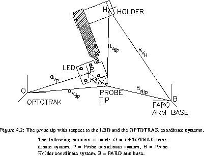
As shown in transform, the mean position of the LEDs as
determined by the OPTOTRAK gives the vector  . The
position of the tip of the probe in the OPTOTRAK reference system is
given by the vector
  . From the figure, it can be seen
that
  can be determined if the vector
  is known together with the orientation of the coordinate system P with
respect to O. The vector
  (constant in the P
coordinate system) was determined by the following procedure.
The probe was rotated about a fixed endpoint (i.e.,  is
constant), 500 measurements were taken and each sample and the
centroid of the LEDs (
 ) was calculated. A least squares fit
was then performed to find the radius and center of the sphere that
best fitted this set of points (since that, during the motion, the
centroid of the LEDs moved on a surface of a sphere). The vector
 was then taken to be center of this sphere.
The next step was to establish the LED coordinate system P with an
origin at the centroid ( ) of LEDs. Unit vectors having
for direction the principal axis of the LEDs,
  ,
,  and
and  , were determined by solving the eigenvalue
problem outlined in [1], and the axis of the probe
coordinate system were taken parallel to these vectors.
Using an homogeneous transformation matrix notation, the transformation
between  and
and  can be written:

where

 was then determined from the inverse of
(4.1):


Once the constant vector  was determined, the position
of the probe tip for any data point was computed using 0vtip.
Note that the transformation matrix in this equation involves the
determination of the axis of the P coordinate system.
Patrice MUNGER
Mon Oct 23 15:09:17 EDT 1995
 . The
position of the tip of the probe in the OPTOTRAK reference system is
given by the vector
  . From the figure, it can be seen
that
  can be determined if the vector
  is known together with the orientation of the coordinate system P with
respect to O. The vector
  (constant in the P
coordinate system) was determined by the following procedure.
 is
constant), 500 measurements were taken and each sample and the
centroid of the LEDs (
 ) was calculated. A least squares fit
was then performed to find the radius and center of the sphere that
best fitted this set of points (since that, during the motion, the
centroid of the LEDs moved on a surface of a sphere). The vector
 was then taken to be center of this sphere.
 ) of LEDs. Unit vectors having
for direction the principal axis of the LEDs,
  ,
,  and
and  , were determined by solving the eigenvalue
problem outlined in [
 and
and  can be written:


 was then determined from the inverse of
(

 was determined, the position
of the probe tip for any data point was computed using 0vtip.
Note that the transformation matrix in this equation involves the
determination of the axis of the P coordinate system.