One of the most fundamental distinctions between and conventional stereotaxy is the use of a global 3-D transformation between the image and surgical spaces. In conventional stereotaxy, since the transformation is performed on a slice-by-slice basis, any local distortion in a region of image space does not perturb the transformation found from slices that are removed from that region. However, in , it is important to ensure that the whole volume is geometrically consistent in order to be able to perform reliable registrations.
Moreover, results of simulations reported in Chapter 3 tend to demonstrate that a means of significantly decreasing the error of registration by homologous point matching is to use a large number of points. Because the number of reliable natural landmarks at the surface of a patient is small, this involves the use of some external set of fiducial markers. These markers could be individually attached to the patient's head or could be fixed to a rigid structure that would itself be firmly attached to the patient's head. In any case, requires that the markers be accurately represented in image space, i.e., that the relative distribution of the markers as deduced from the images be the same as the actual placements.
In order to test the geometrical accuracy of the representation in image space of such a set of fiducial markers, the relative position of the markers must be known precisely. Since a reference structure specially designed for is not yet available, the OBT stereotatic frame (OBT_frame) was employed instead.
This section describes an experiment whose goal is:
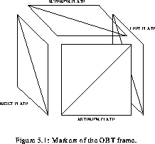
The marker structures visible on MR images of the OBT frame are
CuSO solution filled channels embedded in plastic plates.
Although only four plates were used for the experiment, the frame can
accommodate five, and in each of them, four linear channels form a
perfect square (of 130 mm on a side) with a fifth channel joining
opposite corners of this square. The plates can be fixed on the frame
at precise positions. frameplates shows the 3-D structure
(whose geometry is known to within
solution filled channels embedded in plastic plates.
Although only four plates were used for the experiment, the frame can
accommodate five, and in each of them, four linear channels form a
perfect square (of 130 mm on a side) with a fifth channel joining
opposite corners of this square. The plates can be fixed on the frame
at precise positions. frameplates shows the 3-D structure
(whose geometry is known to within  0.1 mm) formed by the markers
when the plates are mounted on the frame.
0.1 mm) formed by the markers
when the plates are mounted on the frame.
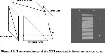
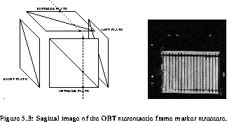
In MRI, it is possible to acquire a volume as a whole in one single acquisition (as distinct from 2-D imaging where the volume consists of a stack of 2-D images). This is achieved by manipulating the spin distribution using three orthogonal gradients in such a way that each sample of the MR signal corresponds to a point in a 3-D Fourier space (k-space). Note that unlike 2-D MRI where only one slice is excited at each RF pulse, the signal in 3-D MRI comes from all the spins in the volume. As in 2-D Fourier MRI, one of the gradients is turned on during the readout of the signal. This gradient is referred to as frequency encoding or readout gradient. The two other gradients are called phase encoding gradients. Although in 3-D imaging, since the data are acquired as a volume, the concept of slice is rather imprecise, and it is conventional to define the acquisition plane as the plane formed by the frequency encoding gradient and the phase encoding gradient that changes the most rapidly. Typically, the orientation can be transverse (x-y plane), sagittal (y-z plane) or coronal (x-z plane), were x increases from left to right, y increases from anterior to posterior and z increases from inferior to superior (with respect to a patient lying supine in the scanner). This convention also defines the orientation of the plane that peels from the 3-D data block most readily, i.e., where data elements constitute a linear vector in computer memory.
Independently of the acquisition plane, the 3-D data can be viewed in any of these planes. trans_framecor_frame illustrate the different slice orientations with respect to the stereotactic marker structure and the appearance of the image for each case. The phantom that appears in these images was not used in the analysis, but provided a convenient way to support the frame and simulated the level of the MR signal encountered in practice.
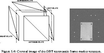
The four corners of the squares formed by the markers in each plate constitute points that are easily localized on the image. Moreover, the position of these corners on the images can be found by fitting straight lines on each linear channel followed by finding the intersection point of the lines found in this manner.