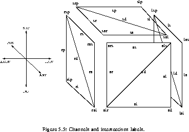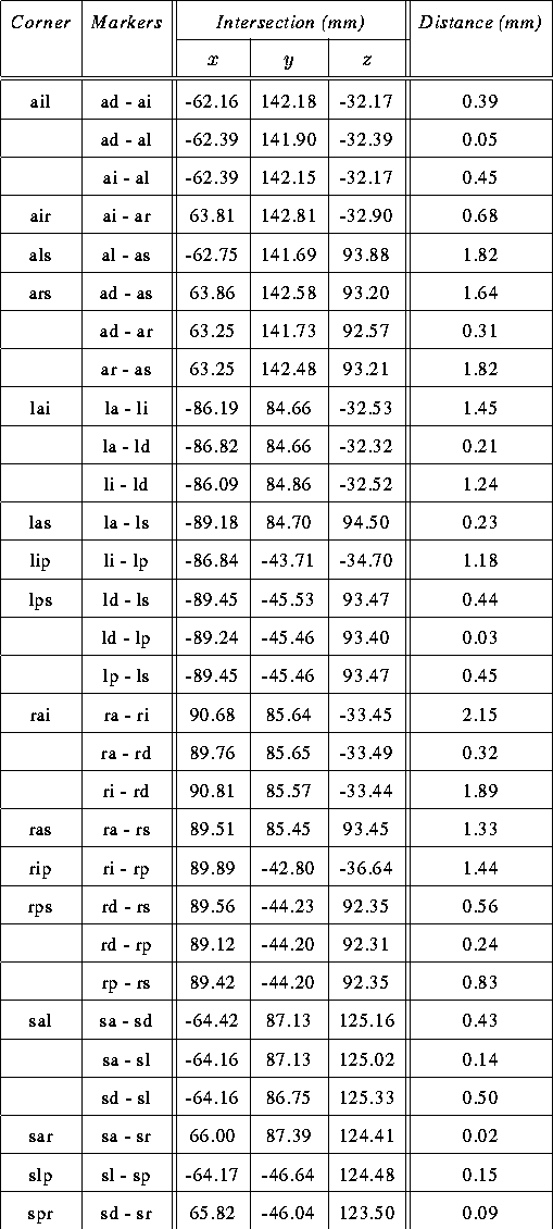
After a line was fitted to every channel, the intersections of the channels were computed using the above formalism allowing the position of the corners formed by the channels to be found. In order to identify each channel unambiguously, a labelling convention was adopted. A channel is identified by two letters: the first one refers to the plate in which it is embedded and the second letter, to the position in the plate (l = left, r = right, s = superior, i = inferior, a = anterior, p = posterior, d = diagonal). For instance, channel li refers to the inferior channel of the left plate and rd refers to the diagonal channel in the right plate. The corners of the square formed by the channels are labeled with three letters. Again, the first one refers to the plate and the other two specify the position in the plate. So, the corner ars specifies the right superior corner of the anterior plate. Note that when a diagonal channel is involved, three different intersections correspond to the same point. The labelling of most of the channels and intersections is shown in labels. The position of the channel intersections of are displayed in inter.


Referring to inter, by looking at the corners defined by more
than one intersection, it is obvious that one cannot consider the
uncertainty on the position of some corners to be less that 1 mm. For
instance, intersection rai shows a difference between the three
intersections of the order of 1 mm. Nevertheless, this 1 mm
uncertainty is not larger than that on the position of the corners
found by direct inspection of the images. This deceiving result is
explainable by the fact that some markers undergo a space-variant
distortion (not only a shift). This distortion suggests that the
linear fit might not accurately match the position of the marker near
the intersection. Moreover, the marker distortion seems to become
more important near the intersection, making any extrapolation attempt
uncertain. However, other intersections corresponding to the same
corner present smaller differences ( 0.5 mm), meaning that in
these cases, the corner positions can be considered to be determined
accurately.
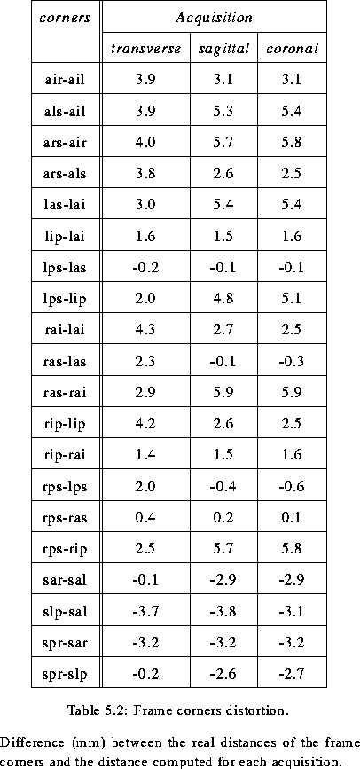
Distances between various corners were computed using the data of inter, and diff shows the difference between the known distances of the frame corners from manufacturer's specifications, and the distance computed for each acquisition. For corners defined by several intersections, the intersection between the two orthogonal channels was taken as the corner position. Note that, in order to avoid any potential error due to the misplacement of the plates on the frame, only the distance between corners embedded in the same plate were considered.
