|
The magnetic field generated from a single thin wire can be calculated by the Biot-Savart Law:
 (1)
(1)where r is the distance from the wire, I is the current
in the wire, and  (2)
(2)
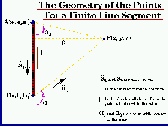
(Click image to view enlarged version) The generalized equation for a line segment at any point in space was determined to be (see Figure 2):  (3)
(3)where  (4)
(4)
 (5)
(5)
 (6)
(6)
The summation of each component of the magnetic field at the point P contributed by each small line segment along the coil is the total magnetic field at that point. The total magnitude of the magnetic field at point P is simply the square root of the sum of squares of each component magnitude. The Experimental Measurements of the Magnetic Field

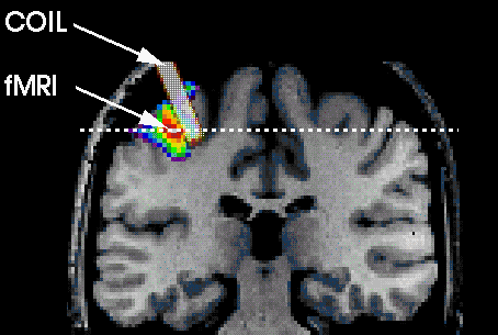
Figure 3: A virtual rod and an MRI image of a stimulated brain Figure 3 depicts a Magnetic Resonance Image of a human brain which was stimulated by a TMS coil. The virtual rod shown in the figure is the placement of the TMS coil's center on the subject. This image is of importance since oncethe distribution is determined, the rod will be replaced with the exact location of the peak focused magnetic field. This will enable the researcher to find the correlation between the induced change in brain activity with the 3-dimensional magnetic field distribution produced by the TMS coil. The magnetic flux density B
is similar to the electric flux density D. As where The magnetic flux through a surface S is given by where

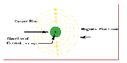
Figure 4: Magnetic flux lines due to a straight wire with current coming out of the page (Click image to view enlarged version) Micheal Faraday in London and Joseph Henry in New York discovered that a time-varying magnetic field would produce an electric current. A static magnetic field produces no current flow, but a time-varying field produces and induced voltage (called electromotive force or simply emf) in a closed circuit, which induces a current flow. Faraday discovered that the induced emf, Vemf (in volts), in any closed circuit is equal to the time rate of change of the magnetic flux linkage by the circuit. This is called Faraday's Law and it can be expressed as:  (10)
(10)where N is the number of turns in the circuit and The induced voltage for a conductor system C is given by [5]: or  (12)
(12)Any physical effect whose magnetic field dependence is precisely known can be used for the measurement of magnetic fields. Many methods are used to measure steady fields but for pulsed field, only a few of them remain of practical interest. Many of the methods used to measure steady fields cannot be used in pulsed operation because their frequency response is insufficient. The Spherical Magnetic Probe (SMP) used here for the measurement of the magnetic field intensities produced by TMS was designed according to the Inductive Magnetic Probe design [5]. The method most used for measuring pulsed fields is based on the simple pickup coil. When a solenoidal coil with an effective area S is placed in a time-varying magnetic field H, the induced voltage Vi(t) at its terminals is:  (13)
(13)The coil has N turns, each of cross-sectional area A, and is placed with its axis parallel to the field lines. Therefore, we can write where Sa is an additional active area formed by the leads and connections; in carefully prepared probes, Sa can be limited to less than 1 mm2. [5] From equation 13, it follows that the
magnetic field is proportional to
|
